SPECIAL REPORT: Extending mole-sieve life depends on understanding how liquids form
Well-designed, monitored, and operated molecular sieve dehydration systems in natural gas processing plants effectively remove moisture for more than 2,000 regeneration cycles. Numerous plants, however, experience moisture breakthrough with newly installed molecular sieve.
When good molecular sieve material is used and dehydration problems exist, they commonly result from a few process design oversights not identified during original detail design.
Retrograde hydrocarbon condensate by itself or with excessive heat rate during regeneration, stagnant piping traps, and undersized separation tend to be leading causes of chronic molecular sieve underperformance. Elongation of the mass transfer zone and subsequent early moisture breakthrough (channeling) in molecular sieve dehydration beds have been the major operational economic failing in many BP-operated gas plants.
Once root causes are identified and remedied, however, molecular sieve units can perform for more than 2,000 regenerations without channeling and with minimum maintenance.
This article discusses causes that commonly go unnoticed during original design and are not always considered during troubleshooting. This article also discusses other causes of molecular sieve underperformance and summarizes experiences from several BP operated plants around the world.
The article also explains design shortfalls and describes installed remedies and resulting molecular sieve performance, along with some operational and design tips that help extend molecular sieve life and performance.
BP performance
Historically at BP, molecular sieve dehydration underperformance has played a large role in degrading several processing plant operating economics. Specifically, this dehydration underperformance has resulted in annual mole sieve replacement (and associated decrease in plant throughput or availability), chronic reduction in plant capacity, long-term reduction in NGL recoveries, and shutdowns to remove ice and mole sieve dust from brazed aluminum exchangers at various sites.
Some of BP’s NGL plants experienced moisture breakthrough from the molecular sieve dehydration units within days of initial service or early molecular sieve replacement; some have required bed replacement after fewer than 400 regenerations (1-year operation). Other plants have operated for decades without having to replace molecular sieve and perform per design for more than 2,000 regenerations (5 years’ operation).
What explains the discrepancy in performance? Also, other than following published design guidelines, working with molecular sieve manufacturers during the design phase, and purchasing good molecular sieve, what can be done to ensure molecular sieve dehydration performs per design for more than 2,000 regenerations? What are the fundamental problems experienced with existing systems and what can be done to improve performance?
Liquids
Liquid contaminants (hydrocarbons and water) generated from one or a combination of retrograde condensation, stagnant piping pockets, poor separation, or excessive heat input rate during regeneration have been leading causes of poor molecular sieve performance and reduced plant economic performance within BP.
The presence of free liquids (either hydrocarbons or water) in a stream expected to be 100% vapor results in chronic early breakthrough or channeling. Responding to symptoms and not to the cause exacerbates dehydration problems.
Examples of secondary problems include excessive dust formation, mechanical failure of support screens, accelerated channeling, and possibly contamination of downstream equipment with mole sieve dust.
Free-liquid damage
Liquids can damage molecular sieve via several mechanisms. Regardless of the mechanism, however, the net effect in each case is an elongation of the mass transfer zone and subsequent reduced moisture removal capacity and channeling.
The following summarizes established molecular sieve damage mechanisms:
- Liquid hydrocarbons block access to micro pores. This slows the mass transfer rate of moisture adsorption plus the heavier hydrocarbons tend to crack during regeneration and permanently restrict sites for moisture adsorption.1
- Liquid droplets hitting the molecular sieve tend to act like a hammer and mechanically crush the sieve.
- During regeneration, liquid hydrocarbons reflux around the vessel wall and cake into a donut-shaped solid agglomerate along the interior wall of the vessel.2
- Also during regeneration, liquids refluxing at the top of the bed can lift the top layer of support balls and the top few inches of molecular sieve. Sieve movement results in increased dust formation (through abrasion) and movement of the support balls disrupts flow distribution and creates a nonhomogeneous flow profile.
- An excessive heat input rate during regeneration creates water refluxing at elevated temperatures that destroys the molecular sieve binder.3
Along with channeling causing ice or hydrates in downstream processing, other problems tend to crop up. Specifically, operational personnel respond with what they control: increase regeneration temperatures, decrease cycle times, and increase regeneration-gas flow rate.
All of these responses may increase dust formation and formation of agglomerates, which then escalate channeling and reduce moisture removal capacity. The problems are typically tolerated until mole sieve changeout. New molecular sieve is sometimes installed with a guard layer, but the channeling may still occur as before.3
When specifying molecular sieve designs, designers normally assume the feedstock is 100% vapor. Sometimes this is correct, but this assumption is the leading cause of poor molecular sieve performance. Even with good separation upstream, liquid hydrocarbons can still form.
How can this be?
Retrograde condensation
Dehydration may occur with gas at its hydrocarbon dewpoint, that is, downstream of liquid-vapor separation. It is common, however, that gas at its hydrocarbon dewpoint experiences a natural phenomenon called retrograde condensation.
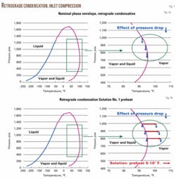
Fig. 1a illustrates a typical phase envelope drawing and the impact of retrograde condensation. Any drop in pressure between the separator and the outlet of the molecular sieve bed will cause liquid hydrocarbons to form via retrograde condensation process.
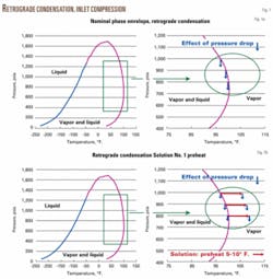
• Solutions to retrograde condensation: preheat. Preheating the inlet gas 5-10° F. ensures that condensation cannot occur between the separator and bottom inches of the molecular sieve dehydrator (Fig. 1b). Preheating with a waste energy stream such as propane-refrigeration compressor discharge (in parallel with existing propane condensers) or residue-gas compressor discharge provides for efficient energy sources. Alternatively, other heat sources can be considered.
Three BP locations have installed preheaters (two after original plant start-up) and have extended mole sieve replacement to more than 2,000 regenerations from fewer than 500, and the incremental adsorption temperature had no negative effect on NGL recoveries.
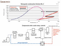
• Solution to retrograde condensation: after-compression temperature control. Gas leaving inlet compression (and upstream of mole sieve adsorbers) requires good temperature control. Excess cooling of inlet-gas compression upstream of molecular sieves can result in retrograde condensation (Fig. 2a).
This hydrocarbon condensation is further exacerbated in fall and spring operations and when piping dead legs exist (described in Fig. 3a). Installing good temperature control after compression provides the same result as installing inlet preheating.
At one North Texas plant, tuning of temperature-control loops along with installation of variable frequency drives (VFDs) on the inlet-gas compressor after coolers (Fig. 2b) was part of the solution that enabled the plant to increase dehydration capacity (and subsequent plant capacity) to 48.0 MMscfd from 36.0 MMscfd.
Liquid traps in inlet piping
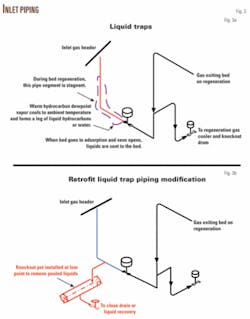
Piping around molecular sieves is prone to high stresses due to thermal cycles. Hence, piping design focuses on a routing that minimizes the effects of thermal stresses. This can sometimes result in liquids pooling upstream of the molecular sieve dehydration bed (Fig. 3a).
Between the wet gas header and the inlet isolation valve is a stagnant piece of pipe. During the regeneration cycle, this pipe and its contents have the potential to cool to dewpoint temperature pending the gas composition, which is a problem if the temperature of the wet gas entering the dehydration unit is above atmospheric.
As the vapor cools, water and hydrocarbons can condense and remain in the stagnant leg. When the regeneration cycle (heating and cooling) is over and the inlet isolation valve opens, these liquids are forced into the top of the molecular sieve bed with the inlet gas. This mechanism and the damage it causes are repeated as it recurs with every regeneration cycle.
To solve inlet piping traps, various piping arrangements can be made for new or old installations. Fig. 3b describes a drain system installed at one facility to remove the stagnant liquids that had pooled.
Liquid traps in regeneration pipe
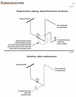
As with hydrocarbon condensation from wet inlet-gas piping, both hydrocarbon and water vapor condensing in the regeneration-gas piping can occur with poor piping design.
During the regeneration cycle, warm to hot, water and hydrocarbon-saturated gas leaves the top of the molecular sieve bed. This stream immediately cools upon contact with the regeneration-gas outlet piping. Hydrocarbon and water condensing ensues.
When the bed goes from cooling to adsorption, the inlet isolation valve opens and the pooled liquid flows to the top of the molecular sieve bed. Fig. 4a describes a commonly installed liquid trap in regeneration-gas piping.
Since this is a piping design flaw, numerous solutions are available. Fig. 4b shows the modification installed at one facility
Poor upstream separation
Poor vapor-liquid separation and a lack of redundancy in level control indication on separators are leading causes of problems in gas processing in general and molecular sieve dehydration specifically.
As a rule, the bigger the separator, the better the bulk separation of vapor and liquid. A large separator with a demister pad upstream of molecular sieve dehydrators, however, does not guarantee sufficient vapor-liquid separation. This is because there will always be some liquid carryover, be it sub-µ-size mist or slugs of liquid.
Bulk separation followed by coalescer-type filters on gas streams upstream of molecular sieves (and on regeneration-gas streams from reciprocating compressors) is essential for keeping liquid hydrocarbons and free water out of the molecular sieve. Both separation devices require redundant level indication to minimize the possibility of carryover.
In the case of retrograde condensation, however, good separation upstream of dehydration will not prevent hydrocarbon liquids from forming and damaging the mole sieve.
Other problems, contaminants
Among other problems and contaminants are methanol injection, mechanical damage, poor regenerations, depressuring and repressuring rates, isolation valve, and inlet distribution.
Methanol
Methanol injection in gas gathering pipelines is a common method to inhibit hydrate formation. Methanol adsorbs considerably more on 4A sieve than 3A. Replacing 4A sieve with 3A was part of a success story at one BP facility. Before changing to 3A sieve, NGL tariff limits should be researched to determine whether methanol passing through the sieve into the cryogenic process exceeds NGL specifications for allowable methanol in the NGL product.
Mechanical damage
The support screens on which the molecular sieve sits tend to be made of thin stainless steel. Molecular sieve dehydrator vessels generally consist of 2.5+ in. thick carbon steel. When hot regeneration gas (usually 450-550° F.) flows into the vessel, the stainless-steel support grid undergoes a rapid thermal expansion and corresponding increase in diameter.
The carbon steel vessel ID is virtually unchanged, on the other hand, because there is more mass and less relative surface area for heat transfer and thermal expansion of carbon steel wall is less than stainless steel. Hence the rope packing between the support screen and the vessel becomes compressed.
As the regeneration continues, the vessel wall warms, and the ID grows when cooling gas is applied, the thermal cycle is reversed. That is, the support screen shrinks quickly and the vessel ID slowly decreases. In large-diameter molecular sieve vessels, the difference in metal growth and shrinkage between the support screen and the vessel becomes significant.
Specifically, molecular sieve dust and extrudate or spheres tend to fall into the rope packing. After numerous regeneration cycles, the rope packing begins to lose its elasticity due to the solid material. The support screen then loses the ability fully to expand and the longer screens tend to buckle.
Buckling has ranged from minor (with no operational problems) to major (in which the molecular sieve fell into the cavity beneath the support screen). In the latter, pressure drop across the bed increased and channeling (on both adsorption and regeneration) was exacerbated. Operators’ response may be to increase regeneration temperature and reduce cycle times, worsening the problem.
If the system lacks appropriate instrumentation or is not monitored, the support screen problem may not be identified until the vessel is opened for the molecular sieve replacement. Replacing or repairing the screens can add weeks to the molecular sieve changeout time (which reduces plant availability). Proper instrumentation and daily monitoring of regeneration and dust-filter pressure drop help identify a problem and prepare adequate plans before vessel entry.
Where the bed had collapsed through the screen, there were several mechanisms used to resolve the issue. First was installation of a preheater on the inlet gas to prevent retrograde condensation. Second was to switch to 3A sieve and regenerate at 475° F. instead of 550° F. Thirdly, due to the switch to 3A, the methanol adsorption decreased and the water capacity increased to the extent that the regeneration could be extended. The extension was sufficient that a two-staged heat input was used during regeneration.
Hence the difference in thermal expansion between the support screen OD and the vessel ID was reduced. Fourthly, “L” flashing was added above the rope packing to minimize the dust falling into the rope packing.
For new installations with large diameter adsorption beds, absolute tolerances in diameter grow. Therefore, there is a greater chance for varying radii (e.g., egg-shaped vessels). The more egg-shaped a vessel, the greater the chance for the support screen to lack the necessary growth clearance. Hence, vessel ID taken at 45° and sent to the screen manufacturer before ordering the support screen is recommended. This enables thermal expansion of the grid to occur without binding.
Poor regenerations
Well designed molecular sieve systems have staged heat inputs in the regeneration process. This reduces the risk of water reflux damage during the regeneration cycle.1
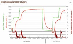
Fig. 5 illustrates a regeneration cycle in which heat input is controlled to prevent water condensation and reflux and to minimize mechanical damage to the vessel internals due to excessive thermal stresses.
Also, poor regenerations in well designed systems tend to cause anomalous problems. Power outages, control system failures, and spikes of water in the inlet gas can all lead to insufficient moisture removal
Daily monitoring with process historian data provides a simple mechanism to ensure dehydration is complete and can reveal poor regenerations before they become a problem. Fig. 5 presents an example of regeneration data that are examined daily.
The heat during this regeneration may appear to be excessive, however; during adsorption the bed was exposed to a larger than expected amount of moisture and the heat cycle was extended (and the cooldown cycle shortened) to ensure a thorough regeneration.
Depressure, repressure rates
Rapid changes in bed pressure in the switch from regeneration to adsorption or the switch from adsorption to regeneration can lift the bed, which increases dust formation and can result in heterogeneous bed depth (and the possibility of gas channeling). Published information suggests a maximum rate of pressure change no greater than 0.8 psi/sec.
Isolation valves
Valve leakage can mask good molecular sieve performance. Use of proven isolation and switching valves minimizes moisture mechanically slipping by the molecular sieve beds.
In addition to valve leak testing at the factory, isolation and switching valve seat testing should be considered at site in particular if it can easily be adopted into pneumatic testing during precommissioning.
Furthermore, dehydration system logic and valve stroking should also be fully validated as part of precommissioning.
Inlet distribution
Layers of ceramic balls on the top and the bottom of the molecular sieve bed are low-cost measures to prevent channeling during adsorption and regeneration in addition to proper inlet-gas distribution devices.
References
- de Bruijn, Jacques, N.H., Huffmaster, Michael A., van de Graaf, J.M., van Grinsven, P.F.A., and Grottjans, H., Maximizing Molecular Sieve Performance in Natural Gas Processing, 81st GPA Annual Convention, Dallas, Mar. 11-13, 2002.
- Rastelli, Henry, and Stiltner, Julie, Extending Molecular Sieve Life in Natural Gas Dehydration Units, 86th GPA Annual Convention, San Antonio, Mar. 11-15, 2007.
- Meyer, Peter, Hydrothermal Damaging of Molecular Sieve and How to Prevent It. GPA Europe Conference, Paris, Feb. 21, 2003.
Based on a presentation to the 87th GPA Convention, Grapevine, Tex., Mar. 3-5, 2008.
The authors
Robert J. Bombardieri is gas processing consultant for BP Canada Energy Co. Previously, he was business development director for BP. He has also held numerous positions in several countries for BP and its heritage companies, Amoco and Dome. Bombardieri graduated from the University of Alberta with a BSc (1983) in chemical engineering and Tulane University with an MBA (2001). He is a professional engineer in Alberta.
Theresa Elizondo is a senior process engineer at BP America Inc., Houston. Her current position is with BP’s E&P Technology Group, operations and engineering team providing process engineering support for operations and projects worldwide. She holds a BSc (1988) in chemical engineering from the University of Texas at Austin, after which she was hired by Amoco Corp.
