Multilaterals extend well-life offshore Thailand
Cliff Hogg
Cliff L. Hicks
Weatherford International Ltd.
Houston
Cham Soon Hoe
Weatherford International Ltd.
Singapore
Weatherford International Ltd. helped design and install a four-well multilateral (ML) in Bualuang field offshore Thailand, converting existing wellbores into MLs quickly and at low risk. ML technology eliminated the need for new wellheads and additional platform slots, avoiding significant additional drilling costs.
Rig contract obligations and Thai government delays in starting work on the first well caused an original seven-well ML plan to shrink to four wells. A hollow-whipstock Level 4 system was installed on all four.
Level 4, as defined by the Technology Advancement of Mulitlaterals (TAML) group, provides maximum mechanical support at the junction, which is created in a cased section of main bore and uses a liner anchored back into the main bore and cemented at the exit point.
Although industry has used MLs since the 1990s, this installation involved an operator with little ML experience. The industry also had little ML experience in this region. Lack of operator experience led to increased vendor participation earlier in the project than sometimes occurs.
The operator needed to sidetrack from an existing 95⁄8-in. wellbore into a soft sandstone formation above the target. The junction required maximum mechanical support because of shallow junction depths and resulting weak formations.
A short timetable and limited rig availability restricted crews to using minimum specialized equipment and processes. Success stemmed largely from the simplicity and reliability of the ML systems used.
Cooperation and integration between the operator and service providers ensured maximum compatibility. The project demonstrated MLs are feasible on tight schedules and in areas where they are considered newer technology.
The Gulf of Thailand's geology features a series of north-south trending ridges and linear, fault-bounded basins. Tertiary sediments found within these basins are a mix of Oligocene and Miocene source rocks that provide Type I kerogen-generated oils and Type III kerogen-generated natural gas deposits.
This particular ML project was in an area where oil reserves dominate and have fairly low gas-oil ratios. The oil has 27° API gravity and relatively high viscosity. Because of the field's strong bottom-water drive aquifer and both horizontal and vertical permeability of 800 md and higher, water coning and premature water breakthrough often present risks to long-term production.
Discovered in the early 1990s, this Western basin field was estimated as of Dec. 31, 2014, to have proved and probable reserves of nearly 25 million bbl. Development strategy changed drastically as reserve estimates climbed over the years.
The operator focused on long-length (≥500-1,000 m) horizontal wells high in the formation, providing increased reservoir exposure and less exposure to high water cut situations.
First commercial production from Bualuang field began in 2008 with the installation of a 12-slot wellhead platform in 60 m of water. In 4 years, 10 producing oil wells and two disposal wells were completed.
Produced with electrical submersible pumps (ESP) and using gravel packs for sand control, the oil wells began producing at a combined 17,000 b/d. A second platform was installed in 2012, providing 16 additional slots and enabling development of additional reservoir zones.
Within 1 year, overall field production reached more than 25,000 b/d, and all slots on the second platform were in use by January 2014. Costs deterred construction of a third platform. The operator considered abandoning certain wells and using those slots for newer reservoir targets but decided against sacrificing existing production. Instead, the operator sought an ML option to install additional wellbores and increased production.
Modern ML systems are designed for specific wells, resulting in niche markets for different fields and types of wells worldwide. The Gulf of Thailand ML project had numerous operator requirements.
Wellbore protection
The operator requested a Level 4 cemented and mechanically supported ML, seeking a proven system with reliable installation and minimal risk. The operator wanted to ensure existing production would not be lost due to a failure in creating the second wellbore.
Existing producing reservoir pressures were 1,600 psi, and the reservoir was potentially susceptible to damage from drilling fluids during ML installation.
The system had to be installed in near-horizontal conditions while providing full compatibility with conventional rotary steerable systems and polycrystalline diamond compact bits.
Although the operator needed a cemented junction, the new reservoir target would not be cemented or perforated but would follow the same completion process as the original wellbores, with sand screens placed in the open-hole reservoir. After construction and cementing of the ML junction, this technique would require drilling a 7-in. lateral shoe and drilling into the reservoir with a 61⁄8-in. drilling assembly.
The lateral was completed with a sand-control packer and 41⁄2-in. screens. Completion required an ML junction allowing screens and drill bits to be run through the junction without damage. The ML also needed to provide large-bore potential at junction depth to land an ESP and completion packer.
The operator started considering ML options with only 10 months left on the rig contract, meaning all equipment already had to be available or quickly obtainable.
Given key ML requirements, the operator selected a hollow-whipstock, Level 4 system that allowed for downhole installation of a combination casing packer and whipstock assembly, after which a conventional casing exit could be milled as in standard sidetracking.
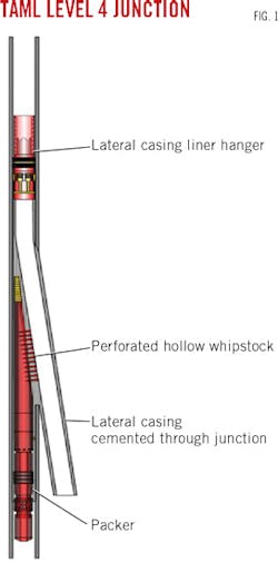
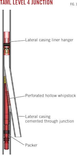
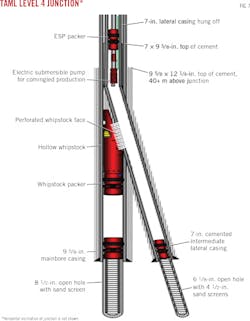
After lateral drilling, a lateral casing would run through a casing exit window to depth, be hung off in the main bore above the junction, and cemented. The lateral bore would be completed using standard techniques and procedures before regaining access to main-bore production. Access to the main bore occurred using perforating guns placed across the lateral casing at the junction and firing through the casing, whipstock face, and into the whipstock's hollow interior (Fig. 1).
Hollow whip-stock
Flow from the main bore lower zone passed through the perforated whipstock and lateral casing after perforation to commingle with production from the lateral wellbore.
The hollow-whipstock approach used overlapping casing strings cemented in place, resulting in a maximum-strength junction. Cement served as a mechanical barrier to sand intrusion, reducing the possibility of premature production loss.
The operator selected hollow-whipstocks to provide both mechanical support and full compatibility with drilling and completion plans. The whipstock had a 2° concave angle compared to the typical 3° angle offered by many other whipstocks and ML systems.
The shallower angle resulted in a longer casing-exit window, which in turn reduced the dogleg severity of the resulting sidetrack and increased drilling capabilities and efficiencies.
The packer and hollow-whipstock system, as well as the perforating assembly, were suitable for horizontal application and capable of providing kickoffs to the left and right of the casing high side. This flexibility enabled the most efficient drilling trajectory for each well.
A hollow whipstock that is later perforated does not require retrieval and can be used to steer the lateral casing through the casing exit and into the lateral open hole, eliminating the need for a bent joint.
Risk analysis of existing production and likelihood of successful additional wellbore installations influenced the operator's selection of the hollow-whipstock ML system. Using a packer system as the anchor method below the hollow whipstock fully protected the existing main bore and production from that reservoir during junction construction and lateral wellbore drilling and completion.
The system was more reliable during installation because it enabled use of conventional casing-exit and drilling techniques and equipment. Not having to remove a whipstock before lateral casing operations also was safer because it eliminated the risk of retrieving the whipstock and reduced time between when the lateral hole was drilled and when the lateral casing could be run and cemented.
ML installations
Mobilization of necessary equipment and personnel began in second-quarter 2014, with the first well installation targeted for late May. With minimal specialized equipment required for the window milling portion, equipment quickly was brought in from elsewhere and readied for use.
But as the project was set to begin, the Thai military declared martial law, making it practically impossible to import perforating guns. The operator put the project on hold.
Work began on the first ML installation in early August. The existing wellbore in production was killed with filtered seawater. The upper completion consisting of an electric submersible pump and 31⁄2-in. production tubing was retrieved.
A wellbore cleanout-scraper run performed in the 95⁄8-in. casing reached junction depth. The bottomhole assembly run on this trip was designed not only to properly clean the casing walls but also to mimic the configuration of the hollow-whipstock system and verify that dogleg severity or tight spots in the wellbore would not prevent the hollow-whipstock system from reaching intended depth.
After getting to the desired depth, a cement bond log (CBL) survey ensured that suitable cement was behind pipe in the area targeted for the junction casing exit. Although lack of cement would not prevent the casing exit window from being milled, it could have led to excessive cement loss during lateral casing cement operations.
The operator confirmed the top of cement was at least 40 m above the intended junction depth. Although the 73° inclination of the well at junction depth initially suggested the CBL survey should be run on pipe, the eventual wireline survey was successful.
With the well properly prepared, operations to run and set the packer and hollow-whipstock system began.
Packer
Run as the lowermost component in the junction construction assembly, the packer isolated the main-bore production zone during junction construction and lateral wellbore completion operations.
The hollow whipstock of this Level 4 ML system was attached above the packer and did not require an independent trip to install. The hollow whipstock allowed later perforation of its concave ramp face, enabling production from the main bore to flow through the packer and hollow whipstock, and then through the perforation holes of the concave face, cement, and lateral liner. This flow-through capability eliminated any need to remove the whipstock, reducing both time and risk.
The whipstock provided a concave ramp to guide the milling assembly against the casing wall to create a conventional casing exit. The shallow 2° angle of this concave face increased the window length and decreased dog leg severity, making the system more suitable for extended reach and rotary steerable systems.
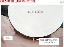
Raised rails on the whipstock's concave face ensured that the milling assemblies did not contact and damage the concave perforation face during milling and drilling operations (Fig. 2).
The milling assembly ran attached to the hollow-whipstock and was designed to provide a complete casing exit window and sufficient formation rathole in a single trip.
The measurement-while-drilling (MWD) system used in this application determined the orientation of the hollow-whipstock before setting and anchoring the packer-whipstock assembly.
The mills flow ports allowed fluid circulation for complete well control. This flow capability enabled use of an MWD assembly above the milling assembly. Alignment of the MWD tool and whipstock face took place at the surface, before running downhole. Flow through the tubing string then provided MWD measurements, allowing the operator to determine whipstock orientation.
By the time the multilateral junction and wellbore were constructed in a second targeted well, political issues had eased enough to allow delivery of the perforating equipment. Crews worked to perforate and regain access in both ML wells.
Perforating
The hollow whipstock assembly created the casing-exit window through which the lateral wellbore was drilled. Perforation of the whipstock through its concave face regained production access from the original mainbore reservoir.
Rails on either side of the concave face kept the milling and drilling assemblies from potentially damaging the 2.5-cm-thick perforation-plate concave face. A 2° concave angle rather than the more typical 3° concave increased the length of concave and therefore the length that could be perforated.
With 2.54 m of perforating length, 33 penetrations were achieved through the concave perforation plate, creating a total flow area of 17.4 cu m.
Proper depth and orientation of the perforating guns was the major factor determining successful main-bore perforation.
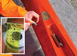
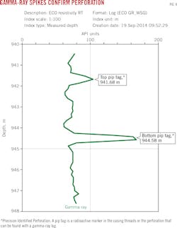
The concave surface carried four radioactive (RA) tags installed on either side at the top and at the bottom of the perforating length (Fig. 3). The tags, although low power at 1-3 microcuries each, provided enough signal for easy detection with a gamma-ray logging tool run as part of the perforating-gun assembly.
The signal confirmed perforating charges were placed at the precise depth needed for complete penetration of the whipstock. Along with RA tags providing proper depth control, the large, hollow pocket area directly behind the 2.5-cm perforating plate of the concave provided sufficient orientation tolerance for the perforating charges to penetrate the hollow pocket, even if alignment was off by 15-20° left or right of the concave center line.
Guns, MWD
Regaining original mainbore production access required running either tubing-conveyed or wireline-conveyed perforating guns to depth, orienting them toward the whipstock face, and firing.
The firing head and activation procedures for this perforating assembly used conventional perforating equipment and methods, but the gun assembly and perforating charges used were developed specifically for this hollow-whipstock system.
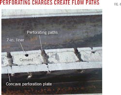
Maximum penetration depth is a goal of standard perforating systems. But hollow-whipstock ML jobs seek perforations that create large, debris-free holes, while limiting penetrative depth and any damage to the backside of the whipstock (Fig. 4). The gun carriage also was designed to fire only along a single axis into the whipstock face.
The MWD system provided orientation of the whipstock assembly before milling the lateral exit window. The same MWD was used during the tubing-conveyed perforating process to orient the perforating gun assembly against the hollow-whipstock concave. The MWD short-pulse detected the precise depth of the RA tags to ensure the perforating charges were properly positioned at the concave face.
Tubing control valve
Determining orientation of the perforating gun assembly required circulating fluid through the drill pipe in sufficient volume to active the MWD system. Firing the perforating gun assembly, however, required application of hydraulic pressure within the tubing string. A tubing control valve between the MWD system and the perforating assembly provided both the flow needed for the MWD and the closed tubing system required for perforating (Fig. 5).
This control valve runs in the hole in the open position, allowing full-fluid communication between the drill pipe and the annulus, the flow necessary to activate the MWD. After proper orientation, three successive cycles of flow increase and decrease shut the communication port and created a closed tubular system.
The tool can cycle back to open if additional MWD measurements are needed. While closed, internal tubing pressure can be increased to the level necessary to fire the guns.
Regaining production
Tubing or wireline can run the hollow-whipstock perforating system. The high inclination of these wells led to using a tubing-conveyed system and MWD orientation. Calculations determined the proper number of pins to install within the pressure-activated firing head to provide a firing pressure of 3,500 psi using a 33⁄8-in. gun loaded with 33 charges,.
Once loaded with charges, the gun assembly and MWD-control valve assembly were aligned and the perforating charge orientation was correlated with the MWD tool orientation. The perforating bottomhole assembly ran to depth without difficulty.
Upon reaching the hollow whipstock's depth, gamma-ray spikes provided by the RA tags in the whipstock and detected by the MWD in multiple correlation passes (Fig. 6) determined precise perforation depths. With the whipstock face providing a casing exit 15° to the right of the high side, MWD oriented the guns at 195° from casing high side (180° opposite the whipstock orientation), resulting in a perforation alignment directly down the whipstock face's center axis.
With the gun charges at proper depth and orientation, the tubing control valve cycled to closed in preparation for firing. The tubing string was pressured up to 2,500 psi at surface and held for 1 min to activate the 9-min delay on the firing head. Crews on the rig floor heard the firing.
A rapid wellbore-pressure drop from 325 psi to 40 psi and a 300 bbl/hr fluid-loss rate confirmed both a succesful perforation and communication with the main-bore reservoir. Surface inspection verified this success.
Workers prepared for the upper completion after confirming communication with the main bore and flow tests. The upper completion used an ESP and packer configuration run on 31⁄2-in. production tubing. It was run and landed without difficulty, and the well began production (Fig. 7).
No cementing issues were noted, and all four junctions were successfully cemented in place, leading to maximum mechanical support. Perforating operations and regained access to main-bore production occurred without incident.
All four perforations with tubing. MWD orientation, and gamma detection happened as intended, enabling proper placement of the perforating gun in all four wells. Firing of the guns succeeded at first attempt in the first three wells. But a faulty firing-pin cartridge on the final well caused an extra trip to retrieve and rerun the perforating assembly. A second perforation succeeded.
Crews confirmed communication with the main-bore reservoir on all four multilateral installations.
Bibliography
Balstad, O., Glaser, M., and Heng, T., "New Single-Trip, TAML Level 4, Multilateral Junction Technology Reduces Well Costs in Norwegian Sea Subsea Well-A Case History,"Offshore Europe Oil & Gas Conference & Exhibition, Aberdeen, Sept. 8-11, 2009.
CCOP-EPF, "Thailand Exploration-Development History," http:/www.ccop.or.th/epf/Thailand_explor.html.
Durst, D., "Multilateral Wells-Low Risk Alternative to Conventional Drilling," Drilling Technology Forum, Ho Chi Minh City, Vietnam, June 12-13, 2003.
Glaser, M. and Balstad, O., "Evolution of Single-Trip, TAML Level 4 Multilateral Junction Technology to Reduce Well Costs," International Association of Drilling Contractors World Drilling Conference & Exhibition, Dublin, June 17-18, 2009.
Hogg, C., Huiban, S., and Timms, A., "Gulf of Thailand Case Study: Multilateral System Expands Reservoir Access from Slot-Limited Platform," Drilling Contractor, Vol. 71, No. 2, Mar. 10, 2015, pp. 80-86.
Khanna M., Comrie-Smith N., Lawlor M., and Virdy, M.K., "Bualuang Oilfield, Gulf of Thailand: A Successful Development Using Geosteered Horizontal Wells," American Association of Petroleum Geologists International Conference and Exhibition. Singapore, Sept. 16-19, 2012.
Redlinger, T. and Constatine, J., "Multilateral Technology Coupled with an Intelligent Completion System Provides Increased Recovery in a Mature Field at BP Wytch Farm, UK," SPE/IADC Drilling Conference. Amsterdam, Feb. 19-21, 2003.
SubseaIQ, "Offshore Field Development Projects, Bualuang," Mar. 3, 2015.
US Energy Information Administration, "Thailand International energy data and analysis," https://www.eia.gov/beta/international/analysis.cfm?iso=THA.
Virdy, M. K. and Adams, S., "Bualuang Oilfield, Gulf of Thailand: A Success Story Utilizing Integrated Field Development Planning," South East Asia Petroleum Exploration Society Exploration Conference, Singapore, Apr. 8-11, 2013.
Based on presentation to Offshore Technology Conference Asia, Kuala Lumpur, Mar. 22-25, 2016.
The authors
Cliff Hogg ([email protected]) is Weatherford's global product-line manager for multilateral systems. He is based in Houston and has been involved in multilateral technology development for 20 years. Hogg has written more than 12 technical papers and articles on multilaterals. He previously served as the program developer and instructor for the Society of Petroleum Engineers Multilaterals Short Course, Hogg earned a BS (1987) in petroleum engineering from Texas A&M.
Cliff Hicks ([email protected]) works as a tubing convey perforating product specialist for Weatherford, and is the author of corporate global procedures and policy for Weatherford. He has 36 years of experience in explosive safety, service delivery, firing systems, and drillstem test tools. Hicks is also a member of SPE, a firing-head patent owner, and obtained a BS (1970) in business from Arizona State University.
Cham Soon Hoe ([email protected]) is Asia-Pacific regional operations manager at Weatherford. He has worked in the oil and gas industry for 15 years, specializing in fishing, casing exit, and multilateral technologies. He holds a BS (2000) in petroleum engineering from the University of Technology, Malaysia.
