Improved proppant placement in glutenite reservoir aids fracturing
Guo Jian-chun
Gou Bo
Southwest Petroleum University
Chengdu City, China
A novel stimulation method in a tight glutenite reservoir with larger thicknesses has shown promise is a field case. The method solves the key fracturing difficulties in these reservoirs and improves stimulation performance, effectively promoting the economic development of such oil fields in China.
The deep tight glutenite reservoir with thick pay zones requires stimulation to achieve commercial production. The stimulation results from Shengli oil field of China have shown that massive hydraulic fracturing (MHF) with single-density proppant is insufficient to enhance production due to poor proppant placement profile.
These wells have thick pay intervals with net pay thickness of 30.5-88.5 m. Covering the entire production zone with proppant is difficult, leading to reduced productivity.
MHF combined with a different density proppant (CDDP), including low, medium, and high density, can improve the proppant placement profile for thick pay zones and has proven effective for increasing productivity.
Glutenite reservoir
In recent years, tight oil development has been greatly promoted in China with the tight glutenite hydrocarbon reservoir attracting attention in particular. This type of reservoir occurs mainly in the Junggar, Nan-Xiang, Bohai Bay, and Song-liao basins in China.
Shengli oil field in Shandong province has many tight glutenite hydrocarbon reservoirs in Bohai Bay basin where development of glutenite oil reservoirs is popular with China's exploration and production industry.1 2 Among these reservoirs, Y104 oil field is one of the most popular.
The sedimentary environment of glutenite reservoirs in Y104 oil field is a nearshore subaqueous fan deposition. It possesses a good condition for hydrocarbon accumulation, close to the central zone of oil generation. The target stratum is the fourth group sand layer of Oligocene Sha-he-jie formation, with a burial depth of 3,400-4,000 m (TVD). Reservoir temperatures range 140°-170° C. with high formation pressure coefficients (1.15-1.30).
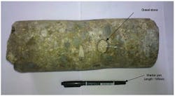
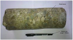
The formation consists of many types of rock, including glutenite, conglomerate, fine conglomerate, fine sandstone, and siltstone. The rock constituents mainly contain quartz, feldspar, and lithoclast. The gravel diameters in the rock are 3-20 mm; some individuals may reach 150 mm (Fig. 1). Therefore the rock is poorly sorted and has lower textural and compositional maturities, which suggests rapid deposition.
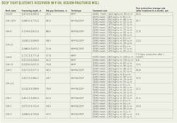
The hydrocarbon pore volume is residual pore with packing, fissure, and secondary dissolved pore. The diversity of depositional environment and lithology in Y104 causes the heterogeneity of reservoir properties, whose formation permeability varies 0.015-22.3 md (average 0.21 md) and porosity of 3.6-27.8% (average 11.5%). The reservoir is considered to have low porosity and ultralow permeability. Most of the wells are vertical wellbores with thick pay zones (see accompanying table).
Improving stimulation
Because the Y104 glutenite formation has ultralow permeability, thick pay zones, and sufficient initial pressure, hydraulic fracturing becomes the optimal stimulation choice before wells are placed in production. Although Y104 oil field was discovered more than 20 years ago, only in 2009 did the field start to undergo rapid development because of the application of ultrahigh temperature fracturing fluid and MHF.
Three wells have been stimulated with MHF in single-density proppant four times, and the post-stimulation production is lower than expected, except for well YG103 (table). So, there is insistent demand for Y104 oil field to improve fracturing technology and increase production.
Productivity improvement is mainly determined by propped fracture length and conductivity, which is controlled by hydraulic fracture propagation, proppant transport, and proper proppant placement.3
In the past, stimulation of the Y104 glutenite formation encountered many obstacles to obtaining the desired proppant placement profile. These obstacles could be summarized into three aspects:
1. The productive interval in Y104 is long, with net thickness of individual layer of up to 88.5 m (table). Proppant settling and convection, therefore, make it difficult to prop the entire fracture height.
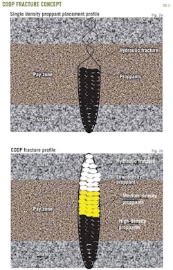
After the treatment, large amounts of proppant settle to the bottom of the fracture and most of the fracture height is unpropped or closed, which decreases the fracture area and reduces production (Fig. 2a). Unfortunately, however, this phenomenon also emerges in the application of MHF.
An important technique in solving this settling is known as combination of different density proppants. The technique involves pumping a high-density proppant with bulk density (BD) from 1,810 kg/cu m to 1,880 kg/cu m, which is beneficial to propping open the bottom of fracture, following the medium-density proppant with BD from 1,650-1,700 kg/cu m and the light proppant with BD from 1,470 kg/cu m to 1,550 kg/cu m.
The low-density proppant helps perfect the proppant placement throughout the entire fracture area, especially propping open the top of the fracture due to low-density proppant's relatively low settling velocity. With this technique, high, medium, and low-density proppants will settle at the bottom, center, and top of the fracture, respectively (Fig. 2b).
However, low-density proppant often is easier to crush than high-density proppant due to its lower strength, which can lead to reduced fracture conductivity and should be considered in a deep well such as in the Y104.
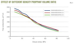
The fracture conductivities for different density assembly are measured in the laboratory. Although the crush occurred in low-density proppant, the experimental results show that the influence of low-density proppant crushing on conductivity is slight under high closure stress due to the small proportion (Fig. 3).
However, perforation position and length also influence proppant placement in the large vertical thickness reservoir. It is very important to solve the problem of how to open the perforations before the frac treatment. The converged perforation was applied to the thick production interval and the perforation position and length were selected by fracturing simulator.
2. Another challenge for ultralow permeability in Y104 is maximizing the effective fracture length. There are two prominent problems for creating a long fracture in glutenite reservoir, including complex fracture geometry and heavy fluid leak-off.
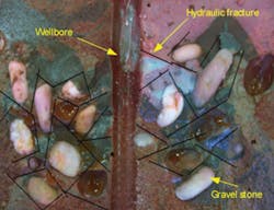
The results of a large-scale hydraulic fracturing simulation experiment on glutenite rock show that hydraulic fracture geometry is complex and fracture network has been observed due to the influence of conglomerate (Fig. 1b), which lead to the difficulty of creating a long fracture. Meanwhile, a large amount of natural fractures in the reservoir aggravate the complexity of the fracture geometry resulting from heavy fluid leaking-off. Apparently, the complexity of fracture geometry will retard proppant transport in the fracture.
The proppant slug was applied to smooth the fracture face and reduce the resistance of proppant transport in the fracture. In general, the slug is designed to carry fluid with proppant concentration range from 108.6 kg/cu m to 144.8 kg/cu m. The size of proppant used in this slug is 40/70-mesh or 30/50-mesh. Simultaneously, MHF with high displacement and fluid loss control agent may be conducive to decreasing the fracturing fluid leaking-off.
3. At last, the reservoir temperatures in Y104 range from 140° C. to 170° C., the fracturing fluid and the downhole instruments must satisfy the MHF demands at such high temperature. The ultrahigh temperature fracturing fluid adapted to 200° C., which could maintain a viscosity of 100-110 mPa.sec when it was continuously sheared for 120 min under the conditions of 198° C. and 170 sec-1. Based on the analysis of the configuration of high temperature and high pressure packer, the self-sealing and compression packing elements were designed. And then the ZY541 packer enduring the pressure of 70 MPa and the temperature of 180° C. was first invented, which provided a suitable tool for the stimulation in these reservoirs.4
Field application
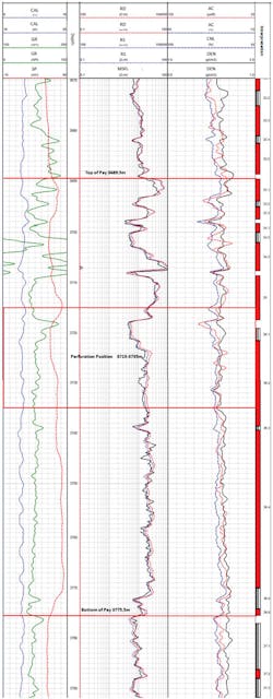
Operators of 104-1 sidetracked hole (STH) agreed to a trial use of MHF with CDDP in the Sha-he-jie formation of Y104 oil field. The well 104-1STH had three thin intervals and one thick interval to be stimulated and show its commerciality (Fig. 4). Both intervals have weak barriers between oil zones with a low stress contrast, insufficient to confine fracture-height growth.
The logging interpretation results show that the objective intervals have low permeability within the scope of 1.8-3.1 md and porosity ranging 7.3-9.4%. The fracturing design of this treatment is to explore the synergism of MHF and CDDP to keep the proppant in the whole production zone uniformly and hence increase the production.
It's important to determine perforation length and position before the treatment. According to the fracturing simulator, with perforation length ranging 5 m to 86 m the influence of perforation length on the propping fracture geometry is very little. However, there may be risk for MHF if long perforation length were adapted, due to narrow fracture width. Considering the converged perforation in the thick pay zones, the perforation length selected was 20 m.
Meanwhile, the simulation results also showed that the effect of perforation position on fracture geometry is not large, but the proppant placement profile is affected significantly by the perforation position. When the perforation position is at the middle-upper pay zones (3,715 m-3,735 m), the proppant may cover the entire pay zones and place uniformly (Fig. 4). If perforation position is close to the top of production zones or the bottom of them, it is difficult for the proppant to overlap all the sections because of proppant convection and settling.
Four types of proppant were used in 104-1STH: 20/40-mesh low density (1,470 kg/cu m), medium density (1,650 kg/cu m), high density (1,810 kg/cu m), and 40/70 mesh (1,810 kg/cu m). The proppant with 40/70 mesh amounted to 8 cu m served as the proppant slug. On the basis of perforation position and length, the 20/40-mesh proppant with three different densities was assembled by the volume ratio, which from high to low was 1.5:1:1, namely high-density proppant was 48 cu m and medium density and low was 32 cu m, respectively.
However, the temporary plugging agent (10 tonnes) was applied to control the fluid leak-off in the natural fissure for creating long fracture. The surface tubing pressure increased by 2 MPa after the temporary plugging agent entered the formation, which shows that fluid filtration was under control.
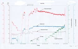
After the proppant slugs and pad fluid, the carrying fluid with 48 cu m of high density (20/40-mesh, 1,810 kg/cu m) was pumped, followed by medium density (32 cu m), and ending with light density (32 cu m), at a desired rate of 7.2 cu m/min (Fig. 5).
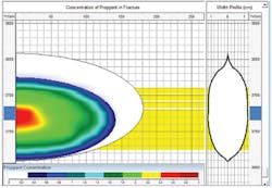
The 104-1STH was a new well. Before the treatment, the tubing pressure was 0.5 MPa with daily oil production of 4.2 tonnes from the 3-mm choke. After the treatment, all the pay zones were propped by the proppant according to the computational solution from fracturing simulator (Fig. 6). The well test interpretation shows that the skin factor improved substantially to -5.518 from -0.15, with dimensionless fracture conductivity reaching to 1.99.
Comparisons of the pre and post-well test analyses showed a production increase of more than 13 times to 55.7 tonnes from 4.2 tonnes at the same choke size. Additionally, the wellhead pressure increased to 12.6 MPa from 0.5 MPa.
Expanded tests
After the successful application in 104-1STH MHF with the CDDP technology, Y104 expanded the technology to the other seven wells. Each well used the CDDP with lumping perforation as the main fracture treatment. The proppant combination was adjusted slightly for different net pay thickness, perforation position and length.
The wells with CDDP technology have shown enhanced zonal coverage and production compared with others (table). Especially, Well 104-6 with reservoir thickness up to 88.5 m and lumping perforation length by 21 m used three different density proppants and treatment sizes to reach 188 cu m at desired rate 7.8 cu m/min, which created a new fracturing record in China.
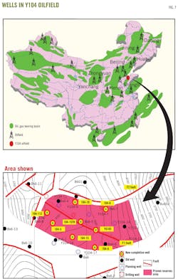
Y104 oil field achieved a production increase after stimulation eight wells. However, the production in Y104 oil field was affected by the fault (Fig. 7). The well close to the F1 fault obtained better post-fracture response than the well near the F2 fault, such as 104-1STH vs. 104-10. But in all, the well stimulated by CDDP had better post-production than the offset well treated by single density proppant, such as 104-10 compared with 104-8 and 104-1STH vs. YG103 (Fig. 7; table). In general, the wells with CDDP have an average increase of 12.6 tonnes/day compared with conventional stimulation techniques.
The CDDP treatments were also performed on three wells near the Y104 oil field, which did not have enough production before the treatment. The three wells, including 109-1 well, 109-2 well, and 109-3 well, had an average production of 14.3 tonnes/day, which exceeded our expectation.
To improve the benefits of CDDP technology continuously, the team has planned extensive pre-job lab tests, including flow conductivity of proppant pack under formation closure stress and fracturing fluid rheological properties under certain reservoir and treatment conditions.
Improvement jobs
MHF with CDDP was extensively applied to the Y104 glutenite reservoir and received good results. The net pressure matching and post-fracture pressure build-up test show that the entire thick production zone was covered by proppant in the vertical direction and the flow conductivity of propped fracture reached to the desired value.
The maximum fracture length, however, is only about 60 m on the basis of interpretation of the well test results of 104-6 well and 104-1STH well, which reduce the increment of the production. In the future, it will be necessary to focus on how to create longer fractures.
Acknowledgment
This article was prepared under the auspices of Sinopec Shengli Oil Field Corp. and Southwest Petroleum University.
References
1. National Energy Administration (www.nea.gov.cn/2012-10/26/c_131931918.htm).
2. Sinopec news (www.sinopecnews.com.cn/info/content/2013-05/08/content_1293940.shtml).
3. Shokir, Eissa M., and Al-Quraishi, Abdulrahman A., "Experimental and Numerical Investigation of Proppant Placement in Hydraulic Fractures," presented to the 2007 SPE Latin American and Caribbean Petroleum Engineering Conference, Buenos Aires, Apr. 15–18, 2007.
4. Jianchun Guo, Yingchun Yue, and Mingshui Song, "The Research and Application of Ultra High Temperature Fracturing Technology for Glutenite Formations," presented to the CPS/SPE International Oil & Gas Conference and Exhibition, Beijing, June 8–10, 2010.
The Authors
Guo Jian-chun ([email protected]) is a professor and the executive president of department of petroleum engineering, Southwest Petroleum University, Chendu City. He holds a doctorate of engineering (1998) from Southwest Petroleum University and is a member of SPE.
Gou Bo ([email protected]) is a PhD candidate in stimulation of oil and gas wells in the State Key Laboratory of Oil and Gas Reservoir Geology and Exploitation at Southwest Petroleum University. He is a member of SPE.
