Ultra-high H2S well-test program prevents exposure during upset
Wu Zhijun
Cui Mingyue
Tang Hongjun
PetroChina Research Institute of Petroleum Exploration and Development
Beijing
A well-test program with emergency hydrogen sulfide (H2S) release response drills successfully limited exposure of facilities and crew to H2S during an upset when safe threshold levels were exceeded. The program was designed based on geological and engineering characteristics of the well in accordance with worldwide testing experiences in H2S-containing oil and gas fields, including national and industrial standards and recommended practices.1-4 H2S is a highly toxic acid gas with strong reducing capacity. It has threshold limit, safety critical, and dangerous threshold limit values (DTLV) values of 10, 20 and 100 ppm, respectively.5 Produced H2S corrodes downhole metal such as pipe strings by three mechanisms: electrochemical corrosion, hydrogen embrittlement, and sulfide stress cracking, resulting in breakage or rupture. To prevent H2S from damaging metal materials used in flow tests, H2S-resistant pipe and equipment should be chosen. Exposure duration and H2S concentration should be minimized if possible. Furthermore, H2S may accelerate aging of nonmetallic materials such as rubber. For personal and equipment safety, H2S should be monitored and operation personnel made aware of relevant requirements.6
Well M test case
Well M is an appraisal well in the Mingbulak structure of Fergana basin, Uzbekistan, which contains two hydrocarbon reservoirs (upper and lower Tertiary). Upper Tertiary is a porous sandstone reservoir, while lower Tertiary is a fractured-porous carbonate reservoir. Each reservoir has an independent pressure system, and the upper Tertiary reservoir has a higher formation pressure gradient. Well M was drilled with a 215.90-mm bit to 5,518 m. For the 4,914.74-5,516.39 m interval, 177.8-mm P110 liner was suspended from 244.5-mm casing and cemented. Subsequently, P110 (4,914.74-3,816.59 m interval) and TP90S (0-3,816.59 m interval) casings were tied back and cemented. The reservoir intervals were drilled with a 149.2-mm bit to 5,918-m total depth. A 127.0-mm Q125 integral liner was hung from 5,389.94-5,914.00 m for completion.
Well design sought to evaluate hydrocarbon potential, ascertain reserves and productivity, identify reservoir characteristics, and locate oil-water contact in the two reservoirs. The geological and engineering characteristics of Well M, based on drilling data and offset-well test data are summarized as follows:
- High temperature and high pressure (HTHP). The formation temperature was 163.8° C. from 5,911 m to 5,899 m in the offset well. Well M encountered high formation pressure at 5,543 m, and the density of drilling fluid was increased to 2.19-2.20 g/cu cm.
- High acid-gas content. The lower Tertiary reservoir in the offset well delivered natural gas with H2S and carbon dioxide (CO2) content of 4.4-5.3% and 2.5-4.5%, respectively.
- High salinity. The reservoir interval has halite and gypsum interbeds. Well test and offset well production showed water salinity up to 36.49 × 10⁴ mg/l. Chloride content in the drilling fluid filtrate rose to 19.50 × 10⁴ mg/l. when Well M was drilled from 5,227 m to 5,232 m. Therefore, salt crystallization is likely to occur during well test, resulting in salt plugging and sticking of the down-hole string.
- Narrow pressure window. A well kick occurred during drilling, but severe mud loss occurred whenever drilling-fluid density was raised (leakage volume was as much as 2,812 cu m during drilling). Low drilling-fluid density, however, also could lead to a well kick, resulting in well control problems.
Well test program
Experiences from Well M provided the basis for a program to safely test the Well A.
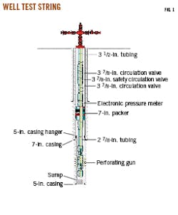
The program consisted of combined perforation and well-test operations. Dual flow and a shut-in procedure were included in the test, taking advantage of the string configuration containing three valves and one packer (Fig. 1). This method was proposed based on existing HTHP testing equipment and technology. After testing the lowest layer, bridge and cement plugs isolated the perforation interval and testing continued upward, layer by layer.
To prevent H2S hazard during test, the following measures were adopted:
- An environmental investigation was made surrounding the well site, layout of surface equipment, and arrangement of materials. Hydrogen sulfide and sulfur dioxide (SO2) detecting devices were installed and debugged at all places where oil and gas leakage might occur (such as those close to the separators, wellhead, and relief outlet).
- Personal protection equipment (PPE) was prepared, including positive pressure air breathing apparatus.7
- Safety training was carried out, and anti H2S drills for operation personnel were conducted at well site.8
- Down-hole string, tools, and instruments were selected based on the requirements of temperature, pressure, and sulfur prevention.9
- Emergency shut-off devices were installed, such as emergency shut-down (ESD) valves for surface equipment). A pilot torch and a remote ignition device were installed both at outlet of the relief line and gas vent of the separator to ensure produced H2S could be burned and timely shut down could be executed in case of emergency.10
- Basic zinc carbonate was added into working fluids which might contact oil and gas, so that H2S could be removed from the killing fluid. Whenever the content of H2S in the produced liquid was high, it would be removed by pumping a desulfurizer at surface.
- A report was prepared titled “The Field Response Plan for H2S Leakage,” and operation personnel were qualified to properly handle any possible H2S leakage.11
Well-test program application
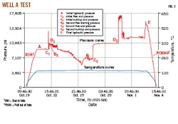
Installation and debugging of well test equipment in Well M preceded drifting and scraping. Testing started on Oct. 19, 2018. From Oct. 19 to 22, perforation guns and test string were run in hole, depth calibrated, wellhead changed, and pressure test conducted. Annular pressure and tubing pressure were subsequently raised to 2,260 psi and 4,132 psi, respectively. After a 5-min wait time, perforating guns were detonated.
The well was shut in for 2 hr. After that, tubing pressure was maintained between 460 psi and 1,200 psi for about 30 hr as pressure was intermittently released from the upstream sampling port. Released liquid volume totaled 870 l. An oil bloom was observed Oct. 23 with 0.825-g/cu cm oil density at 60° F. Hydrogen sulfide concentration was 15 ppm. From 15:25 on Oct. 23 to 10:00 on Oct. 27, an adjustable choke and choke bean were used for the test. Produced liquid was guided into the separator. Cumulative liquid volume from the buffer tank was 36.05 cu m. At 10:00 on Oct. 27, a 10/64-in. adjustable choke was installed, and gas was metered at the gas vent of the separator. Hydrogen sulfide concentration measured by H2S probe at the separator exceeded 100 ppm (150 mg/cu m), and a high H2S concentration alarm was displayed.
Since H2S concentration in the air near the separator exceeded DTLV, for safety of personnel and equipment it was decided on site to:
• Activate the field response plan for H2S leakage.
• Immediately implement emergency search and rescue.
• Limit personnel entering the high H2S-concentration zone.
• Require positive pressure air breathing apparatus and portable H2S and SO2 detectors for personnel entering the zone.
• Minimize test duration if data acquisition and sampling were completed and burn sour gas completely if possible.
• Pump desulfurizer at surface to remove H2S in produced liquid.
Once the desulfurizer was pumped, H2S levels declined to safe levels (Table 1) and testing was completed on Oct. 27. Oil productivity was 15.81 cu m/day and gas productivity was 2,086 cu m/day with a 10/64-in. choke and 798 psi tubing pressure. The oil had 42.89° API gravity and was free of water. Three tubes of pressure-volume-temperature (PVT) analysis gas samples (20 l.) and three tubes of PVT oil samples (600 ml) were taken at the separator. Three tubes of atmospheric oil samples were also collected. Hydrogen sulfide content was 44%, CO2 content was 2%, gas relative density (to air) was 1.07 (compared to 0.5-0.7 for normal gas), and oil density was 0.812 g/cu cm. There was no basic sediment and water (BS&W).
On Oct. 27, 6,178 psi was applied to the annulus, the rupture disk safety circulation valve was opened, and the well was shut in downhole (725 psi was applied inside and outside the tubing). Reverse circulation was conducted to displace fluid at 1,450-1,885 psi pump pressure and 320-240 l./min flow rate. A total of 24.4 cu m of liquid was displaced and 13.78 cu m of oil recovered. The well was shut in again from Oct. 27 to Oct. 30 for pressure build-up analysis, resulting in 826 psi tubing pressure and casing pressure (Fig. 2). After the test, 88.2 cu m of drilling fluid with a density of 1.5 g/cu cm was reverse circulated at 725-1,450 psi and 500-700 l./min to displace test fluid in the annulus and string. Drilling fluid density at entrance and outlet was the same (1.5 g/cu cm), indicating that the well was successfully killed. Finally, the perforation gun carrier and testing string were pulled out and the reservoir sealed, completing the well test.
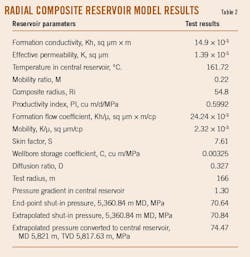
The test not only measured oil and gas productivity and delivered samples, but it also supplied pressure and temperature curves to derive reservoir parameters, per test deliverables (Table 2).
References
- Zhuang, J., “Brief Analysis for Testing Technology of Gas Well with High H2S Content,” Well Testing, Vol. 11, No. 6, 2002, pp. 57-59.
- Qiu, J., Zhang, M., Cai, B., He, Q., Jiang, W. and Dai, Q., “New advances in high efficiency test technology for ultra-deep, high temperature and high pressure hydrogen sulfide gas reservoirs,” Drilling & Production Technology, Vol. 41, No. 2, Mar. 25, 2018, pp. 49-50.
- Zhang, J., Dai, Q. and Zhang, Y., “Identification and control of wellbore safety risks during the well testing of HPHT sulfur gas wells,” Natural Gas Industry, Vol. 35, No. 1, Jan. 25, 2015, pp.120-125.
- Pan, D., Liu, X., Hu, C. and Xiong, Y., “Application of combined operation technology of perforation and test in wells with H2S content in Sichuan and Chongqing region,” Well Testing, 2007, Vol. 16, No. 1, 2007, pp. 42-45.
- Zhang, L., He, Z. and Zhu, P., “Study on workover technology for wells containing H2S in Bohai Oilfield,” Chemical Enterprise Management, Vol.10, No. 3, 2018, pp. 223-224.
- SY/T 6610-2017, “Specification for workplace safety of H2S environment.”
- SY/T 6277-2017, “Code for Personal protection in H2S environment.“
- SY/T 7356-2017, “Safety training specification for H2S protection.”
- GB T 20972.1-2007, “Material for use in H2S-containing environments in oil and gas production-Part 1: general principles for selection of cracking-resistant materials.”
- QSY 1556-2012, “Technical regulation for drill stem testing in high temperature, high pressure, and H2S oil-gas wells.”
- SY/T 7357-2017, “Specification for emergency rescue of H2S environment.”
The authors
Wu Zhijun ([email protected]) is senior engineer of well completion in PetroChina Research Institute of Petroleum Exploration and Development. He holds a PhD in petroleum engineering.
Cui Mingyue ([email protected]) is director and senior engineer of well completion in PetroChina Research Institute of Petroleum Exploration and Development. He holds a PhD in petroleum engineering.
Tang Hongjun ([email protected]) is senior engineer of natural gas in PetroChina Research Institute of Petroleum Exploration and Development. She holds a BS in petroleum engineering.


