Shell drills u-turn lateral well in Permian basin
Robert Hahn
Eric Schumacker
Matt Bowman
Shell Exploration & Production
Houston
In 2019, large azimuth (AZ) pushes while drilling a lateral in the Permian basin, West Texas, led Shell Exploration & Production to execute a 180º turn to drill the lateral back in the opposite direction, creating a horseshoe-shaped well.
Shell used the horseshoe well in March 2019 drilling operations on a four-well pad in a stranded section of the Permian basin. The original plan was to drill two 4,500-ft laterals in Wolfcamp sand and two 4,500 ft laterals in Wolfcamp shale. Drilling issues, however, prevented all but one of the wells. Adding another slot to the pad was not an option, prompting use of the first 180° turn in a lateral drilling. The expertise and data collected from the first horseshoe well will enable calibration of the models for other designs.
Horseshoe well concept
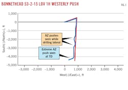
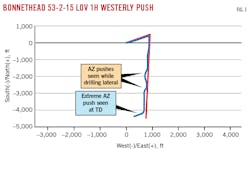
Azimuth pushes in the Permian basin are relatively common while drilling horizontal laterals. Changes in AZ due to formation push are typically in the range of 10-12º/100 ft. In 2019, however, an atypically large AZ push was encountered while drilling Bonnethead 53-2-15 LOV 1H lateral well in Loving County, Tex. Fig. 1 shows that before reaching TD, the wellbore had already experienced two large AZ pushes to the west. As the lateral was nearing TD, it experienced back-to-back AZ pushes greater than 25º/100 ft. Sliding full stands while drilling ahead was unable to stop the push, and in less than 300 ft lateral the wellbore was off-azimuth by almost 60º, resulting in the lateral being almost parallel to the southern lease line of the section.
The well was sidetracked and the lateral drilled to TD at the planned AZ. But Shell questioned whether a 180º turn creating a horseshoe-shaped well could be drilled. A technical assurance analysis was conducted to determine the success of such a trajectory.
Technical assurance
Technical assurance had to integrate both drilling and completions into execution of the horseshoe well. For drilling, the main concerns were how to drill a 180° horseshoe turn, having the ability to transfer weight to the bit in the second half of the lateral, pulling out of the hole with the drilling assembly at lateral TD, and having enough hook load to run casing. For completions, the main concerns were the ability to run plugs on wireline, pull out of hole with wireline, and drill out plugs with coil tubing. Detailed modelling allowed better understanding of these concerns and development of solutions to overcome them.
Drilling
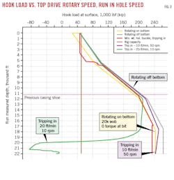
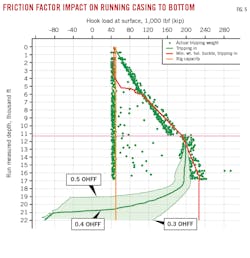
For torque and drag modelling, Bonnethead 53-2-15 LOV 1H was used as an analog for friction factor calibration. Modelling beyond 16,000 ft MD was problematic due to the lack of an analog for friction factors beyond a 180º turn. Sensitivity modelling was done from 20° in the horseshoe to lateral TD with a range of open hole friction factors from 0.3 to 0.5. The high friction-factor case predicted that casing would run on elevators only to 19,000 ft, nearly 3,000 ft short of TD (Fig. 2, green line). Given the absence of offsets, it was difficult to justify narrowing the friction-factor range.
To mitigate the high case friction factor, the plan was to drill the entire lateral, including the horseshoe section, with a rotary steerable system (RSS). This system allows high string rotary speeds to mitigate axial drag and enables continual application of weight to bit and proper steering (Fig. 2). RSS is also critical to keeping the tortuosity of the lateral as low as possible. The success of subsequent well operations like casing running, plug setting, and coil-tubing drill-out were dependent on low wellbore tortuosity and low friction factors.
Two options were considered to mitigate the high case friction factor for the casing run:
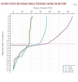
- Casing rotation. Modelling assessed the effects on torque along the string and on hook load when the string is run in hole at different speeds and at different surface rotary speeds. Uncertainty around open hole friction factors made it challenging to predict the surface torque profile and torque required to initialize rotation. Both reducing tripping speed and increasing surface rotary speed are effective in reducing axial drag (Fig. 3). From these guidelines, a baseline for tripping in hole and rotary speeds was selected.
- Casing floatation. The models showed that with a high case friction factor there would not be enough hook-load to run the casing conventionally on elevators. Casing floatation requires a dedicated burst disk to enable a portion of the lateral casing to be evacuated or filled with a lighter fluid, such as base oil, while filling the rest of the casing with active mud. This maintains hook load during casing run with active contributing mud weight in the vertical section while reducing the drag in the lateral with evacuated casing at this interval.
Shell decided to proceed with casing rotation because pumping and rotating would be required with floatation if a tight spot was encountered. Pumping negates any positive effect of casing flotation because the flotation disk must be burst to fill the casing with active mud, instantly increasing drag in the lateral.
Completions
Completions modelling focused on the reach and feasibility of wireline and coil tubing set and drill out plugs. Because effective friction factor calibration was not possible, a tortuous as-drilled offset lateral was superimposed onto the well plan beyond the horseshoe turn, simulating worst-case tortuosity for modeling wireline and coil in the second half of the horseshoe lateral. Modeling showed coil would not reach bottom with a conservative cased-hole friction factor. Alternatively, an aggressive friction factor showed coil getting close to bottom.
These results triggered effective mitigation strategies to ensure the completion was not the limiting factor in implementing the well. The strategy focused on optimizing operations and equipment to get coil to TD. Each aspect of the coil operation was analyzed and reviewed for applicability in a horseshoe well. A workstream developed a fit-for-purpose coil string design in collaboration with the coil tubing provider. The optimized string showed improved reach of 500-1,000 ft in the torque and drag modelling. Specialty agitators, hole clean-up tools, and coiled tubing tractors were also vetted and prepped as aids for coil to reach TD.
The final risk mitigation in case of coil failure to reach TD is dissolvable plugs. Frac plugs are the primary isolation between stages in plug and perforating operations. Composite frac plugs are typically used and are removed with a mill on coil. The problem with dissolvable plugs compared to composite plugs is that they begin to lose integrity as soon as they contact water. To be effective, dissolvable plugs must maintain integrity long enough to isolate frac stages but corrode fast enough to disappear in time for well production. An integrated plan was developed with engineering, operations (water and frac teams), and plug manufacturers to ensure the dissolvable plugs’ effectiveness.
For the plug-running operations, wireline drag modelling showed that, even with a tortuous wellbore, wireline would reach and pick up off bottom within the normal operating envelope of the line. Despite this confidence, contingency plans were developed. The limiting driver of wireline is tension required to pick up off bottom after pumping the wireline bottom hole assembly (BHA) to required depth. The contingency plans revolved around reducing the friction between wire and casing and included coated wireline and friction-reducing chemicals.
Ideal application
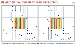
With technical assurance and modelling completed, the horseshoe well was ready to execute. The most attractive location option was on a stranded section in the Permian basin. Most leases in the Delaware basin are 1-mile square sections. Most operators, including Shell, attempt to pool leases together to drill longer laterals. However, some sections cannot be pooled and are thus stranded, meaning that the operator does not have surrounding leases (Fig. 4). The operator is limited to drilling short laterals (about 4,500 ft). By applying the horseshoe concept, the operator can drill four 10,000 ft laterals instead of eight 4,500 ft laterals in a stranded section (Fig. 4).
In March 2019, Shell commenced drilling operations on a four-well pad in a stranded section. The original plan was to drill two 4,500 ft laterals in Wolfcamp sand and two 4,500 ft laterals in Wolfcamp shale. However, complete losses were encountered on two of the four wells while batch drilling the surface holes. Attempts to cure losses and run and cement surface casing were only successful on one of the wells. Adding another slot to the pad was not an option due to restrictions of the location. The only option left was to drill the horseshoe well or abandon one of the laterals and lose valuable production. The horseshoe well was approved.
Drilling
The primary objective of the drilling phase was to limit dog-legs and deliver a smooth wellbore. With that in mind, RSS was used for the lateral and horseshoe sections. Due to past reliability issues with motor-assisted RSS, the decision was made to use a stand-alone RSS. Drilling the first leg of the horseshoe went as planned and both the bit and RSS performed well.
The first major problem and decision point for the team came at the start of the horseshoe section. Successfully drilling this section of the lateral was critical; if the yields could not be delivered, there was risk of the wellbore crossing the lease line and the drilling team abandoning the second half of the lateral. Given that the RSS was performing as desired and bit condition was good, the decision was made to keep the BHA in the hole to drill the horseshoe. The horseshoe was designed on 8.5º/100 ft, the required turn rate to enable eight wells per section with 660-ft spacing between laterals.
Yields with the RSS were less than expected, however, and after drilling the horseshoe about 400 ft the highest dog-leg was just under 8º/100 ft. At this point the trajectory was behind plan and the horseshoe needed just under 10º/100 ft to complete the 180º turn. The RSS was tripped out of hole so that the section could be finished with a bent-sub motor. A 2º motor and agitator were run in hole and the team was able to successfully complete the horseshoe to plan. After completing the turn, the motor was tripped and the RSS was run back in to drill the second half of the lateral.
With the horseshoe completed, the drilling team was now in uncharted territory. Pick-up and slack-off weights were taken at regular intervals to confirm friction factors and torque and drag models. Due to concern about pick-up weights and drag, the team back-reamed out of the hole for any trips in the second half of the lateral until the BHA was through the horseshoe. Throughout the entire drilling phase, Shell’s Houston-based directional drilling center (DART) closely monitored drilling parameters to ensure successful execution.
The second major decision point centered around how to run casing successfully to TD. A relatively low 0.35-or-less open-hole friction factor would enable casing to run conventionally to bottom. Any friction factor higher than 0.35 would require rotation or flotation (Fig. 5). The team decided against floating the string and the final surveys and model calibrations confirmed that, if needed, there was a high likelihood of being able to rotate to bottom.
The following resources were available to help with the casing run:
- High-torque connections on the entire casing string.
- A casing running tool (CRT) rigged up before reaching the horseshoe section.
- A rotatable casing hanger.
- Engineering support from Houston to location
The casing running progressed according to plan and the decision was made to forego the CRT and continue running the casing conventionally because the data suggested low friction factors. The entire casing string was run to bottom without rotating or washing. To land out the string, the rotatable casing hanger was picked-up, but the string slacked-off and landed in the wellhead without any rotation. The cement job was pumped without issues.
Completions
The primary completion objective was to ensure effective plug setting and drill out. During drilling operations, coil and wireline modelling was conducted daily using as-drilled surveys to ensure that no major changes to contingency plans were necessary. Actual trajectory was less tortuous than initial model projections. By the end of the well, modelling still showed that coil would not be able to reach bottom with a conservative friction factor. With the as-drilled trajectory survey in hand, plans for frac, coil, and wireline were finalized.
Plug and perforating operations were completed with dissolvable plugs in the toe of the well, where there was uncertainty about coil reach. Wireline modelling accurately predicted no issues picking up off bottom within the normal operating tension of the wireline. All plugs were set without issue.
The horseshoe section of the lateral was left incomplete to prevent over capitalizing the fracture treatment of the rock. Baseline strategy for 2-mile laterals was implemented on the first attempt to drill out all plugs. Coil was able to reach all the way to TD on the first run. Additional time was spent ensuring the first half of the lateral was clean of plug parts and sand before entering the horseshoe and the second part of the lateral. The fit-for-purpose coil designed for this well never left the yard.
The authors
Robert Hahn ([email protected]) is a senior well engineer at Shell Exploration & Production Co. (SEPCO) in Houston, Tex.. He holds a BSc degree in chemical engineering (2005) from Texas A&M University.
Eric Schumacker ([email protected]) is a staff well engineer at SEPCO in Houston, Tex. He holds a BSc degree in petroleum and natural gas engineering (2014) from The Pennsylvania State University and is currently pursuing an MS degree in computer science at Rice University. He is a member of the Society of Petroleum Engineers (SPE).
Matt Bowman ([email protected]) is a completions engineer at SEPCO in Houston, Tex. He has also served as well intervention engineer and completions supervisor at Shell. He holds a BSc in mechanical engineering (2014) from the University of Texas, Austin.
