Carbon capture and storage (CCS) project sanctioning requires reasonable estimates of CO2 storage volume and plume migration in the reservoir. Numerical simulation based on geological data provides insights into CO2 reaction mechanisms in the reservoir and subsequent storage capability. Fine-scale grid modelling over such a volume, however, may require prohibitively long run times.
Petrobras has presented a workflow to simulate CO2 storage in such large-scale projects. The workflow combines classical and standard approaches to reduce simulation times by 95% over fine-grid numeric modelling. Model runs of two saline aquifers using the workflow show similar accuracy in CO2 trapping mechanisms to a fine-grid model in terms of volumes and plume shape.
CCS modeling
For long term CO2 storage, CCS requires reservoirs with appropriate porosity, permeability, temperature, and pressure. Proper sealing is mandatory to contain CO2, but extensive faulting or fracturing leads to leakage. Knowledge of geomechanics and geochemistry minimizes risk of fault reactivation and caprock breaching.
Carbon dioxide sequestration occurs through four mechanisms: hydrodynamics, solution trapping, residual trapping, and mineralization. Fault stiffness and reservoir compaction also drive long-term CO2 volume trapping.
Reservoir simulation estimates storage volume, pressure limits, and CO2 plume shape. Accurate modelling must include all four sequestration mechanisms, requiring extensive data to account for geochemical reactions, CO2 solubility in water, and acid reactions. Core-flood tests, sour-gas geochemical reactions, mineral dissolution or precipitation, combined fluid corrosivity, caprock capillary entry pressure, Poisson’s ratio, and Young’s modulus are required laboratory data.
Numerical simulation models must include compositional variations from reservoir or aquifer fluids, relative permeabilities, and capillary pressure hysteresis at fine-grid scales to accurately simulate plume migration. These scales, however, result in excessively long run times and therefore are typically applied to benchmark models, small models, or specific reservoir areas. CCS simulations must encompass 1,000 years of storage to ensure CO2 remains in the reservoir, and central processing unit (CPU) usage for CCS applications is higher than in carbon capture, utilization, and storage (CCUS) applications in which CO2 is extracted from reservoir for other applications. For CCS, fine scales can limit modeling studies of real-field applications.
CO2 sequestering workflow
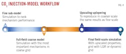
Petrobras presented a workflow to reduce CPU times for large field-scale CCS simulations. It uses common commercial reservoir simulator techniques such as single-phase upscaling, dynamic grid sizing, and high-resolution submodels. The workflow applies to injection and post-injection equilibration stages but neglects geomechanical effects, caprock modeling, and unstable flow-derived CO2 fingers. It is limited to pure CO2 injection without injectivity issues and models the reservoir isothermally.
The primary step in the workflow selects the most relevant sequestering mechanisms such as CO2 dissolution in brine, hysteresis in relative permeability curves, and mineralization using a high-resolution 2D sub-model containing 10 × 10-m horizontal and 1-m vertical gridblocks. The simulation accounts for hundreds of years of injection and storage.
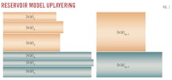
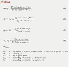
Single-phase upscaling reduces the number of gridblocks in the second step by representing heterogeneity of finer gridblocks with a coarse cell of equivalent properties. Justification for the single-phase approach came from other modeling studies for unstable gas flooding in heterogeneous media with coarse grids, single-phase upscaling, and grid coarsening. Fig. 1 and Equations 1-4 illustrate the grid-coarsening method.
If a finer model is not available, computation time may not suffer but the model will lose accuracy. Simulation accuracy is therefore obtained using local grid refinement (LGR) of a coarse model. The cell is divided from a parent into child cells, subdividing cell properties to reflect local reservoir and fluid interaction variations. If a simulation threshold limit determines that dynamic gridding is not required, the cell is reformed into the parent for computational efficiency.
Reservoir workflow test
A high-resolution grid-scale synthetic model of a saline aquifer undergoing CO2 injection tested the workflow concepts. The model included 432,000 10 × 10-m horizontal and 1-m vertical grid blocks using a single-phase flow upscaling technique in the Petrel commercial reservoir simulator to create a coarser grid model with 240 grid blocks, each 150 × 150-m horizontal and 8-m vertical in size. Calculated CO2 properties came from the Peng-Robinson pressure-volume-temperature (PVT) equation of state and Jossi, Stiel, and Thodos viscosity models, matched to laboratory data. Relative permeability and capillary pressure curves (Kr-Pc-Sw) were fitted to laboratory data using the Corey power law function for relative permeability and Masalmesh’s correlation for capillary pressure.
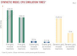
CO2 was injected into the center of the model; 80,000 tonnes over 5 years, corresponding to 4% of the total pore volume of the aquifer model. Fig. 2 shows CPU times of the models with and without mineral reactions. Fine-grid model simulations are green, coarse grid simulations are blue, and dynamic grid simulations are yellow.
The fine-grid model runs the longest and increases CPU times to 105 hr from 20 hr when mineral interactions are considered. This five-fold increase in CPU time is generally observed in the other models. The coarse-grid model required low CPU times (0.05-0.1 hr, depending upon mineral reaction calculations) while the dynamic-grid model yielded significantly higher times, though less than the fine grid model.
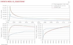
The inconsistency with the higher-resolution model shows that simulation requires a fine grid when fluid saturation changes are high. Dynamic grid refinement imposes a fine grid under these conditions. The dynamic-grid model closely matched the fine-grid model in CO2 uptake, plume radius, and saturation values. CPU times for the dynamic grid model were generally 4–5 times shorter than the fine-grid model.
Real reservoir model validation
Real-world validation of the workflow came from a modeling study of a sandstone aquifer in Campos basin, Brazil. Reservoir minerals are mostly quartz and feldspars, with significant granitic lithoclasts. Total porosity is about 25% from secondary matrix contraction. Average rock horizontal permeability is 200 md from grain dissolution or grain fracturing. Fluid properties are the same as in the synthetic model.
The numerical reservoir model contained 150 × 109 cu m of pore volume with 3.5 × 10⁶ grid blocks. Grid blocks were 250 × 250-m horizontal and 10-m vertical in size. The model injected CO2 for 5 years with a constant rate of 300,000 tonnes/year through the bottom layers of a deviated injector at the center of the aquifer.
The high-resolution simulation required a sub-model containing porosity and permeability distributions with similar averages to the field-scale model. Sub-model simulation includes all mechanisms for CO2 sequestering in a saline aquifer. Based on the results, the mechanisms were ranked in importance for application to the full-field scale model. Mineral reactions were neglected in the upscaling step for full-field simulation because there were no mineralization or dissolution reactions in more than 500 simulated years of injection as the rock matrix contains mainly low-reactivity sandstone.
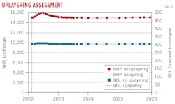
Single-phase upscaling preserved main petrophysical heterogeneities. Fine vertical grid blocks were upscaled to reduce the number of numerical layers to 88 from 473. Coarse horizontal grid blocks were left in their original condition and were dynamically refined in the last step of the simulation. Fig. 5 shows that well-injection rate (QGI), bottomhole pressure (BHP), and CO2 plume shape are similar between the original and uplayered models (both with a 250 × 250-m horizontal grid) with QGI and maximum BHP imposed as constraints.
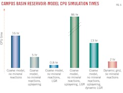
The first three blue bars in Fig. 6 represent the original coarse 250 × 250-m horizontal grid model. A refined LGR 50 × 50-m horizontal model, without mineral reactions, ran for 86 hr (green). CPU time reduced to 13 hr by adding uplayering, and horizontal dynamic grid refinement reduced CPU time to 2 hr. Plume shape is similar for the model with uniform LGR and the uplayered model with dynamic grid. Average saturation inside the plume is 22% for LGR model and 20% for the uplayered model, following smoothness expected during upscaling.
With both the synthetic and real saline aquifer cases in this study, the workflow showed that upscaling with single-phase methods available in commercial packages reduced CPU times by more than 95%.
Based on “Offshore CCS: Addressing Current Barriers for Storage Implementation in Geological Formations,” OTC-32499-MS, Offshore Technology Conference, Houston, Tex., May 1-4, 2023, and “A Practical and Innovating Workflow to Support the Numerical Simulation of CO2 Storage in Large Field-Scale Models,” SPE-215838-PA, SPE Reservoir Evaluation & Engineering, June 20, 2023.
About the Author
Alex Procyk
Upstream Editor
Alex Procyk is Upstream Editor at Oil & Gas Journal. He has also served as a principal technical professional at Halliburton and as a completion engineer at ConocoPhillips. He holds a BS in chemistry (1987) from Kent State University and a PhD in chemistry (1992) from Carnegie Mellon University. He is a member of the Society of Petroleum Engineers (SPE).
