Fiber optics profiles real-time temperature across horizontal lateral
A fiber-optic distributed temperature system (DTS) across a horizontal wellbore off Trinidad provided valuable information and benefits such as identifying areas of oil and gas production along the reservoir interval, verifying production philosophies, correlating logs taken over the reservoir interval, and logging continuous, real-time temperatures across the entire well length.
BP Trinidad Energy Co. (BPTT) installed the system in its Mahogany Bravo-12 well Borehole 01 (MB12B01), on Sept. 19, 2002.
This was the first successful attempt to have a fiber-optic temperature sensing system installed across the sand face of a horizontal well.
To date, some discussion still persists over the final interpretation of the results; however, BP can use the data collected to manage and plan future projects better.
Mahogany field
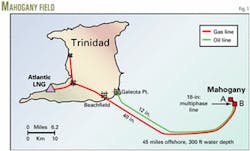
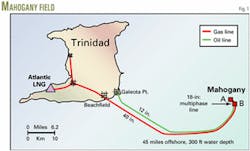
Mahogany field, in the Columbus basin 45 miles off southeast Trinidad (Fig. 1), currently produces 475 MMscfd of gas and 38,000 bo/d.
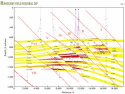
The field has 15 major pay reservoirs in seven distinct fault blocks (Fig. 2). It has one oil reservoir, the 21 Sand. The reservoir extends laterally across Fault Blocks 4 and 5. The oil lies below a 400-bcf gas cap.
MB12B01 is one of 14 horizontal oil wells that drain the thin oil column in the 21 Sand. The well has a 3,500-ft lateral in Fault Block 5 and a TD at 15,453 ft measured depth (MD). It was completed with screens between 11,953 and 15,543 ft MD.
The well penetrated the 21 Sand at 9,915 ft true-vertical depth subsea (TVDSS) and encountered the gas-oil contact (GOC) at 10,018 ft TVDSS. The well cut a 598-ft net gas pay interval.
The well did not see the oil-water contact (OWC) because the horizontal section was drilled at 10,028 ft TVDSS, 10 ft below the GOC.
Within the 3,500-ft horizontal section, the first 1,563 ft was oil-bearing, identified by the little or no crossover on the density-neutron porosity logs; however at 13,516 ft MD, the crossover increased and the next 1,937 ft is interpreted as a gas-flushed zone.
The gas zone is attributed to gas-cap coning, caused by a nearby well, MA10.
The 3,500-ft lateral section was 99.8% sand, (gamma-ray log readings < 90 API).
The 29 wells in Mahogany field have had many different types of completions during the past 5 years as follows:
Openhole horizontal screen only.
Openhole horizontal gravel pack.
Cased, perforated, and gravel packed.
Cased perforated and frac packed.
A fiber-optic flowmeter was installed in the horizontal gravel-packed well MA15 on Mar. 6, 2002. This success led to the next step of installing DTS fiber optics.
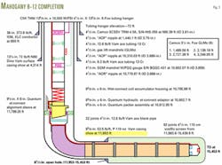
The fiber-optic flowmeter provided valuable downhole two-phase flow information together with a single-point temperature and pressure reading. The DTS, on the other hand, generates a continuous temperature profile along the entire length of the well, including the 3,500-ft lateral section (Fig. 3).
DTS
The Sensa-Schlumberger DTS consists of a continuous optical fiber placed inside a steel control line along the entire well length, from the wellhead to the toe. The optical fiber was pumped from the surface (wellhead) to a turnaround sub at the toe and back to the surface.
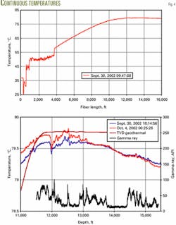
The system provides multiple temperature readings at 1-m intervals every 1/2 hr (Fig. 4).
The temperature profile, if calibrated and interpreted properly, can indicate the areas of oil and gas production from the lateral section, and more importantly, the resulting dynamic profile indicates the reservoir inflow behavior over time.
The subsurface team and completion engineers consider this installation an ideal test for the DTS technology. The unplanned drilling into a gas zone during the final length of the lateral section resulted in production of two distinct phases. Therefore, the DTS may identify regions of varying phase production.
The completion included several specially designed downhole components.
Screens
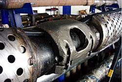
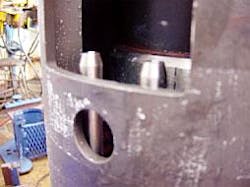
The screen included a groove for the flatpack and dovetail clamps (left photo). The right photo shows the mid-joint screen clamp (Fig. 5).
The special screen design included a groove along the entire length of the screen shroud that housed the clamped steel, flatpack, dual-control line carrying the optical fiber (Fig. 5). Dovetail clamps at each end of the screen joint also secured the flatpack lines within the groove.
A mid-joint break in the screen body allowed placement of a specially designed mid-joint cable clamp. SLHT-S (seal-lock high torque–S) timed connections on the screens aligned the flatpack encapsulated control line along the entire length of the lateral screen section.
SLHT-S are premium-thread connections that line up the joints in the same position every time they are torqued up. This arrangement ensured a continuous alignment of the control line, thus aiding in easy installation.
Clamps
As mentioned previously, special LaSalle mid-joint clamps fit in the mid-joint break along the length of the screen sections. The clamp has to hold and firmly clamp the 18-mm wide flatpack control line within about a 1-ft section of the mid-joint break.
In addition to these mid-joint clamps, the installation included dovetail clamps set within the grooves on the outer shroud of the screens to secure the flatpack control line further. The control line simply snapped into the dovetail clamp at the ends.
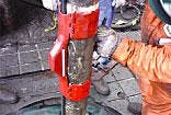
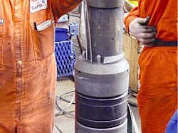
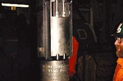
The installation also required special Cannon clamps, placed above and below the Schlumberger formation isolation valve (FIV) and the Quantum multiport packer (QMP), because of the larger diameter offset of these tools on the completion string (Fig. 6). As a result, these clamps secured the flatpack control line around these sections.
null
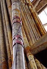
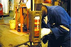
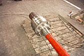
Apart from the screen clamps, the upper completion included LaSalle clamps to secure three control lines (Fig. 7), the dual flatpack encapsulated control line, the downhole permanent quartz gauge (PQG) control line, and the surface-controlled subsurface safety valve (SCSSV) hydraulic control line.
null
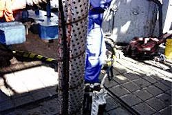
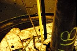
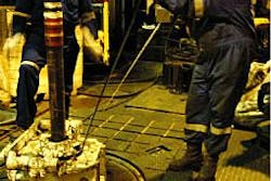
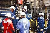
During the running of the completion, the bowl and slips required sufficient recess to allow for the safe containment of the control lines when the slips were closed (Fig. 8).
The slips had a high initial potential for damaging the control line, but proper selection and use of the equipment mitigated this potential problem.
Packer
This completion included a Schlumberger QMP packer equipped with a hydraulic wet-connect system that was needed for running the completion assembly. The packer also contained a special non-pressure sensitive (NPS) kit to prevent setting the packer prematurely.
The system allows fluids to be pumped down the packer bore while running the completion string in hole.
Wet-connect design
Installation of the Schlumberger hydraulic wet-connect system has two parts.
null
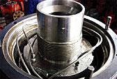
First, the crew runs the control lines through the QMP packer, passing beneath the sealing elements and emerging above them (Fig. 9). The two control lines are then guided into the wet-connect chamber, where they are fastened and terminated.
At this point, two male ends directed upwards mate with the second part of the wet connect system on the seal assembly. This creates the required continuous pathway from surface to the toe of the screens.
The packer included an alignment sleeve to guide the seal assembly of the upper completion into place.
null
The second part of the hydraulic wet-connect system consisted of the seal assembly equipped with an alignment key. The seal assembly had two female ports directed downwards that mated with the two male ends above the packer (Fig. 10). The crew connects the control lines to the seal assembly wet-connect system before the assembly is run in the hole.
A swivel-locking lever releases as the seal assembly comes into contact with the packer. The packer alignment sleeve and alignment key on the swivel produce the proper orientation for mating the wet connect.
Water pumped down the control line during the mating cleans any debris from the connection area and provides a positive indication of connection, such as a pressure rise.
The over pull from the snap latch while spacing out also provides another indication of a proper orientation.
Tubing movement
This completion requires a minimum amount of tubing movement.
Tubing stress changes can produce movement during start-up, shutdown, and the changing production life. After pumping the fiber, however, any tubing movement, especially expansion, would cause the optical fiber to break, resulting in a system failure.
To counteract this problem, simulation runs with Landmark Graphics Corp.'s WellCat software determined the required set-down weight on the tubing as the tubing hanger was landed. The well data used in the simulation software included tubing size, fluid data, well deviation summary, and expected flow rates.
The applied compressive force at the packer stops potential tubing movement, thus creating a system with minimal to no tubing movement to prevent the fiber-optic system from breaking.
Based on this design, the seal assembly included only 4 ft of seals as compared to the usual 15 ft, typical for Mahogany wells with this production profile.
Wellhead
The wellhead had three major alterations to its typical design in Mahogany wells. These changes were done on the tubing hanger, seal flange, and control-line exit blocks.
null
Most wells in Mahogany field use a tubing hanger that allows for two control lines, namely those for the downhole PQG and the SCSSV. This well, however, had no less that four control lines through the tubing hanger, the two mentioned previously plus the two from the DTS dual-control line (Fig. 11).
As a result, the completion required a special tubing hanger for passage of four control lines instead of two.
Crews typically wrapped the two usual control lines inside the tubing hanger bowl before directing them outwards through the exit ports. Following this, they placed the seal flange on the wellhead.
For this completion, however, the tubing-hanger gallery was too small to accommodate all four lines and allow for a minimum 2-in. bend radius on the DTS control lines.
As a result, the completion needed a modified seal flange. This was done by milling off the length of the internal upset of the seal flange to allow more space within the hanger bowl to wrap the additional control lines.
The completion also included a special surface isolation device for the termination of the control lines.
BPTT engineers had considered the possibility of a control-line rupture downhole, either directly beneath the packer or at the sand face. This would allow hydrocarbons to travel up the control line to surface, thus posing a potential fire-explosion hazard on the platform.
To prevent this, Sensa-Schlumberger provided a special surface isolation device that consisted of an isolation chamber and valve to shut in the control lines at surface. This device was required only for the two fiber optic lines. The other control lines had a normal exit block attached to them on the wellhead.
Installation experience
The Mahogany team and BPTT consider the installation of this DTS fiber- optic system a completion engineering success.
The specially designed screens were ideal for the installation of the DTS system. The grooved shroud design, dovetail clamps, and mid-joint clamps all served to secure the flatpack control line properly and make the installation as easy as possible offshore.
An important aspect of the flatpack installation on the screens was the size of the dovetail clamps. These need to be sized properly to allow for the secure placement of the flatpack line within them.
For future wells, the flatpack line dimensions should always be used to ensure that the dovetail clamps are made correctly.
The use of SLHT-S timed connections is absolutely necessary for the installation of this system. These connections reduce the variation in the alignment of the flatpack along the length of the screen section, as well as speed up the installation due to the quick torque turn make up of the screens.
Flatpack alignment for the DTS is extremely important because during the fiber pumping stage, minimal variation reduces friction and aids in a successful installation. During the DTS installation, there were two additional control lines in the system as mentioned previously. This required careful handling and attention to ensure that lines were not damaged during the installation.
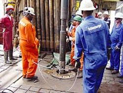
Special attention had to be placed to the two control-line sheaves in the derrick (one for the PQG and the other for the DTS flatpack), as well as for the setting and removal of the slips.
This completion used a pneumatic slip with a large enough recess. This allowed secure control-line placement while the slips were set around the screens or tubing. This is necessary to prevent the control lines from being damaged or kinked, which can cause pumping problems.
The hydraulic wet-connect system was the most important part of this completion. This system had to have proper quality assurance-quality control (QA-QC) both onshore and offshore to prevent any damage.
The damage of this vital part would mean abandonment of the DTS completion if no backup system was present.
The use of this system was successful. All personnel respected the requirements of careful handling and cleanliness when handling the wet-connect kit on the packer and seal assembly.
A point to note is that the male ends of the wet connect above the packer are unprotected and could be damaged by running tools past them before landing the upper completion.
After placement of the seal assembly into the packer bore, a successful hydraulic seal was obtained from the wet-connect system, allowing the second stage of pumping the optical fiber to proceed.
In the event that the wet-connect hydraulic seal was not obtained, the DTS fiber pumping procedure would have been aborted, resulting in loss of the investment.
All personnel involved in the installation were satisfied by the performance of the wet-connect system.
A successful DTS installation requires the use of simulation software for predicting and minimizing tubing movement during the life of the well. The software package used simulated different production scenarios and pressure systems on the tubing. This helped to determine the safe production rates and pressure-testing techniques to minimize tubing movement and maintain the integrity of the system.
Application of the equipment into the specially designed wellhead with separate exit block areas for the DTS control lines and the usual SCSSV and PQG control lines was a success.
The onshore stack-up tests were the most important step for ensuring a successful offshore installation. All the appropriate personnel involved in the installation of the wellhead and control-line exit block systems were present during the onshore run.
The tests involved running the control lines in the modified tubing hanger, installing the exit block-surface termination systems, and finally pumping the fiber through the wellhead.
The onshore exercise proved invaluable for practicing the critical operations of wrapping and securing the control lines within the hanger bowl, installing the modified seal flange, and installing the surface isolation devices.
The tests resolved any operational issues that may have hindered efficient installation offshore. As a result, the offshore installation was time efficient and had no problems.
Thus the stack-up test onshore can be regarded as an essential for the first-time installation of such a system.
The MB-12 well had problems during the pumping of the optical fiber through the dual control lines. The fiber was pumped around the entire length of the first side of the dual control line and through the turnaround sub. But it went no further than the wet connect area on the return side. Therefore, the work did not achieve a complete fiber installation.
The fiber length that was not pumped served for calibrating the system. Thus the lack of this fiber length on the return side posed only a small problem in the initial calibration.
This problem did not handicap the DTS performance.
The pumping problem was attributed to the high friction pressures experienced while pumping the fiber through a well of this length and deviation profile.
In future installations, the wet-connect design will have less coils in the DTS accumulator housing and the fiber path will be further streamlined through the wet connect.
This installation sheds light on the complications of pumping fiber in wells with severe deviation profiles and long horizontal sections.
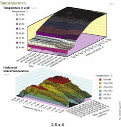
Fig. 12 shows some results obtained from the DTS.
Acknowledgments
The authors thank BP Trinidad Energy Co. for permission to publish the paper and all of the Mahogany team that contributed to the success of this project.
The authors
Lawrence Ramnath is a completions engineer currently working in the Mahogany asset team for BP Trinidad and Tobago. Ramnath has a degree in chemical and process engineering from the University of the West Indies.
Shelley DaCosta is a petroleum engineer in the Mahogany subsurface team for BP Trinidad and Tobago. She previous worked as a facilities engineer for BP and as an environmental research assistant at the Caribbean Industrial Research Institute (CARIRI). DaCosta has a BS in chemical and process engineering from the University of the West Indies.
Sean Akong is lead completions engineer in the Mahogany delivery unit for BP Trinidad and Tobago. Akong has a BS in chemical and process engineering from the University of the West Indies.
Hamid Hassanali is lead operations engineer in Mahogany field for BP Trinidad and Tobago. He previous worked on artificial wells in both thermal and waterflood schemes and designed, monitored, and optimized high-rate offshore gas wells. Hassanali has a BS and an MS in petroleum engineering from the University of the West Indies.
Dickson Omonze is currently assigned as Schlumberger completions DESC (Design & Evaluation Services for Clients) engineer for BP Trinidad and Tobago. His oil field experience encompassing wireline logging, well testing, drill-stem testing, perforating, and sand control. Omonze has a bachelors of engineering in mechanical engineering from the University of Benin, Nigeria.
Based on a presentation prepared for PennWell's High-Tech Wells conference, Galveston, Feb. 11-13, 2003.
