Liner tie-backs stop casing leaks in Libya completions
A project in which existing 7-in. liners were tied back to surface then cemented stopped casing leaks in the Sarir and Messla oil fields in Libya.
Many wells operated by Arabian Gulf Oil Co (AGOCO) in the fields have 7-in. liner completions.
Water containing H2S from the Paleocene zone between 5,500 and 6,000 ft caused corrosion that resulted in the 9 5/8-in. casing losing about 1/8-in./year in its wall thickness and eventually led to casing leaks. The water influx into the wellbore dumped water into the producing reservoir, killing it and causing H2S bacteria to spread in the sweet crude reservoir.
Squeeze cementing of these leaks proved to be only a temporary or difficult solution; hence AGOCO initiated the tie-back project.
Well configuration
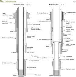
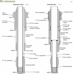
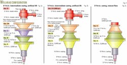
Wells in Sarir and Messla fields have 20-in. by 13 3/8-in. by 9 5/8-in. by 7-in. casing configuration (Figs. 1a and 1b). The wellheads are 13 5/8-in. by 11-in. by 7 1/16-in. by 3 1/8-in. (Figs. 2a-2c).
These wells were drilled in about 45 days and cost about $3 million/well. They either flow naturally or have an electric submersible pump (ESP) for artificial lift.
To accelerate the drilling plan and reduce well costs, the program began installing 7-in. production liner completions.
A major concern was drilling the 12 ¼-in. hole and running and cementing the 9 5/8-in. intermediate casing across a thief zone in the Paleocene below an H2S water zone (8.6 ppg equivalent mud density). This area had complete loss of drilling fluid into the thief zone that required drilling blind and resulted in H2S water dumping from the water zone into thief zone. The zone also caused problems in running and cementing the 9 5/8-in. intermediate casing.
The completion program employed two-stage cementing with limited success. The first stage brought the cement top to the top of the Paleocene. The second stage was pumped after waiting on the first-stage cement to set.
A modified program also included annular casing packers (ACP) in the casing string, just below the stage collar for eliminating the waiting on cement time and to mitigate potential problems after the first-stage cement. Having large OD ACPs, however, caused this casing in many instances to stick off bottom, forcing the casing to be cemented higher than planned.
Faulty 9 5/8-in. casing cement jobs or cement deterioration over time caused the Paleocene water to come in contact with the 9 5/8-in. casing. The water corroded the casing and eventually caused casing leaks that allowed water into the wellbore and into the producing reservoir.
The company employed various approaches to repair such leaks, such as squeeze cementing, matrix cement, and setting ESP packers below leaky intervals. The ESP packers worked for a limited time but problems recurred or other problems developed, such as the inability to unset the ESP packer for workovers because of sediment brought along with the dumped Paleocene water.
The workovers in these wells with stuck ESP packers required the cutting of the production tubing string and ESP cable before running an overshot to jar free the ESP packer.
The leaks work like a nonreturn valve. In other words, when a job attempted to squeeze inside the 9 5/8-in. casing, the leak would not take any fluid or the squeeze pressure would simply bleed off. This made squeezing cement even at excessive surface pressures almost impossible. During swabbing operations, however, such casing leaks profusely produced Paleocene water.
To seal off the leaks, stop dumping Paleocene water into the reservoir, and bring the wells back into production, AGOCO initiated the tie-back project to repair about 60 completions.
Well preparation
The tie-back jobs involved mobilizing a workover rig and killing the wells with established procedures.
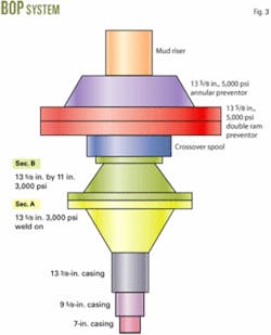
The jobs included installing an 11-in., 5,000 psi blowout-preventer stack after removing the tree and Sections C and B (Fig. 3). The next step involved running an 8½-in. bit and 9 5/8-in. casing scraper on 4 ¾-in. drill collars and 3½-in. tubing to the top of the 7-in. liner, normally set at about 6,500 ft.
A 7-in. casing scraper cleaned the 7-in. liner to about 100 ft below the 7-in. top of liner. A 7-in. drillable bridge plug run and set just below the 7-in. top of liner isolated the perforated intervals during the subsequent operations.
An 8½-in. taper mill run cleaned the entrance of the 7-in. liner hanger receptacle, about 4 ft in length and milled out about 2 in. of steel to ensure entrance for the tie-back stinger. Next, a 7 3/8-in. polish mill run cleaned inside the receptacle. The polish mill can go about 4 ft deeper than the 8½-in. taper mills.
Running tie-back
The tie-back stinger (Fig. 4), prepared locally, consisted of a 7 ft, 7-in. casing joint with a collar at the top and a 45º inclined beveled cut for easy reentry, two 7 3/8-in. OD circumferential ribs spaced 1.5 ft apart for centralizing the stinger, and two ¾-in. ID holes drilled through the casing walls and placed 6 in. above the lower rib for tell-tale purposes.
The tack-welding on the factory made-up collar connection ensured the string’s integrity while cleaning out the tie-back string.
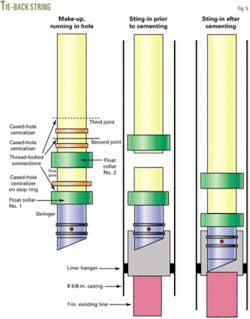
The 7-in. tie-back string (Fig. 5) includes two float collars, spaced one joint apart. These collars ensured the success of cementing in case of a failure in the float in one of them. Thread-locking in the stinger connections and the two float collars ensured their integrity while cleaning out the tie-back string.
The string included the first of the three cased-hole centralizers placed just above the stinger collar with the second centralizer floating above the first float collar, and the third floating above the second float collar. These centralizers center the tie-back string for reentry and ensure a good cement sheath around the bottom of the tie-back string.
The jobs called for filling the tie-back string every five joints during running operation to prevent the string from floating. This eliminated the possibility of trapped air inside the casing prior to circulating and cementing.
Upon the string reaching the top of the existing 7-in. production liner, the job proceeded to run the stinger all the way to the bottom of the 7-in. receptacle before circulating at a high rate. After a drop was noticed in the standpipe pressure that suggested that the stringer holes were out of the receptacle, the procedure called for picking the tie-back string up more than 6 in. to ensure that the bottom circumferential rib was out of the stinger so that no stingers pump out of the receptacle while circulation and cementing.
Circulating continues until the fluid reaches a stable circulating temperature. At this point, cementing of the tie-back string can proceed.
Cementing
AGOCO used three approaches for cementing the 7-in. tie-back string based on the respective well situation and the severity of the leak in the 9 5/8-in. casing.
The first approach used single-stage cementing to bring cement to surface. This involved pumping a lightweight, 10-13.6 ppg, lead cement slurry followed by a small volume of 15.6 ppg tail slurry to ensure good cement around the 7-in. stinger and the bottom two 7-in. tie-back string joints.
This procedure called for a top and bottom cement plug preceded by and followed with good spacers. The spacers were fresh water or a chemical wash. Added friction reducer optimized the slurry cementing and displacement pressures. This approach landed the tie-back string as cemented.
The second approach involved two-stage cementing with the first stage having a slurry volume that covered the annulus to above the top of the leak in the 9 5/8-in. casing. The slurry consisted of a lightweight, 10-13.6 ppg, lead cement followed by a small volume of 15.6 ppg.
This procedure required an 8-hr waiting on cement time before pumping of the second stage. This sealed off a leaky top of liner or a leaky 9 5/8-in. casing. The second stage consisted of lightweight cement circulated to surface.
The third approach was short cementing. When the well had severe losses through the 9 5/8-in. casing leak or the 7-in. top of liner, it indicated that the overlap was not cemented and cementing pressure could exceed the formation leak off pressure below the 9 5/8-in. casing.
In this case, AGOCO used a short cementing approach in which the cement is brought to 150 ft above the 9 5/8-in. casing leak and not high enough to create high pressures (high hydrostatic plus frictional circulating pressures) that may break the formation below the 9 5/8-in. casing shoe.
As in the first two approaches, the third included a lightweight lead slurry followed by 15.6 ppg tail slurry to ensure good cement around the 7-in. stinger and up to 150 ft above it.
The following factors determined the cementing procedure:
- Depth of the existing 7-in. top of liner. A deeper liner top has higher hydrostatic and dynamic pressures imposed by the cementing operation. This may cause the breaking down of the formation below the 9 5/8-in. shoe or losses to a thief zone behind the 9 5/8-in. casing, leading to water influx, flash setting, pumping off the 7-in. tie-back string, or pumping off the stinger.
- Cementing the existing 7-in. liner. This is influenced by the overlap length and cement condition such as a leaky remedial cement squeeze. Most primary 7-in. casing cement jobs end up cementing only the reservoir zone. Shales above the reservoir may wash out severely while drilling the 8½-in. hole causing channeling of the cement slurry. Poor to no cement above the reservoir exposes the overlap.
- The severity and depth of the 9 5/8-in. casing leak. The Paleocene H2S water zone is thick. Some wells have very long leaking zones caused by water migrating up and down the 12½-9 5/8-in. annulus.
- Cement job duration. The job needs to design a point of departure that accounts for all possibilities while cementing. This may lead to over-retardation, long setting times that may cause loss of cement or Paleocene water influx.
- Hydrostatic and dynamic pressures. Pressures that develop during cementing can affect the liner top and leaky 9 5/8-in. casing. This may open the leak further or breakdown the formation below the overlap.
- Cement mixing water. The water is from local water wells and has seasonally variable salinity; so the jobs require lab water tests from the respective source well.
- Paleocene water effect on cement slurry. Paleocene water influx may contaminate the cement or lead to flash setting of the cement, increasing displacement pressures or deteriorating the cement.
- Cement spacer. The design of the spacer should ensure a lengthy protection of the slurry so that it is not contaminated by existing annular fluids that may contain some of the Paleocene water.
- Prediction of fluid and cement loss in the overlap and the leaky 9 5/8-in. casing. The design should include slurry weight and rheology that optimizes cementing and displacement pressures for mitigating fluid losses and influx.
The author
Wathik M. Alhashimi is a senior engineering specialistdrilling, completions, and workovers for the Arabian Gulf Oil Co., Benghazi, Libya. He resides in Calgary. Previously he worked in management and engineering for several other petroleum and oil field service and supply companies in Canada, South America, and the Middle East. Alhashimi holds an MS in petroleum engineering from the Petroleum, Gas, and Geology Institute, Bucharest. He is a member of the Association of Professional Engineers, Geologists, and Geophysicists of Alberta.
