Tests prove out self-powered, wireless, pump torquemeter
Laboratory tests and a field trial in Carmopolis field in northeastern Brazil verified that a self-powered, wireless torquemeter provided a new and better method for determining the reducer torque in a beam pumping unit.
The API recommended calculation for determining torque,1 used for decades, has a 10% uncertainty. This precision has not prevented torque reducer breakage.
The tested instrument measures torque in the reducer shaft with a less than 1% uncertainty, allowing effective control of torque. This torquemeter includes a strain gauge, electronic transduction, telemetry, and LabView software for transmitting the torque signal from a remote unit, fixed in a rotation shaft, to a base unit.
The wireless communication uses the ZigBee standard, which is popular in monitoring applications and industrial control.
Hundreds of experimental tests showed that the system provided high precision, low cost, strength, and high noise immunity, even in environments with strong vibration.
Calculating torque
Beam pumping units, which are the world’s most used method for oil extraction (80% of the world’s wells),2 can have problems with exceeded torque in the output shaft of the reducing gear. When the torque exceeds a certain value, it damages the gearbox whose price can equal 50% of the total cost of a mechanical pumping unit (MPU), rendering it useless.3
Besides the high cost of the gearbox, one also has to consider the lost production during the several days in may take to replace the gearbox.
The method used during decades for calculating reducer output torque in the majority of the pumping units, suggested by API,1 has an uncertainty of 10% for the best operating conditions. This error, however, can be much larger because of decalibration problems of the load cell and accumulation of the error in the sizing of the pumping unit’s parts that enter in API calculation. For the case of ultrahigh-slip engines, errors in computed torque can reach 70%, if one does not consider the inertial effects in a pumping unit’s braking gear calculation.4
The API calculation for determining torque in the shaft does not take into account the structural misbalance with changes in crank angle and the inertial effects of the beam, balance beam, crankshaft, crank counterweight weight, and bearing attrition. The calculation involves 16 variables with each one having a measurement error. The torque calculation reflects the propagation of these errors.
All current studies involving torque measurement in the speed reducing gear of a pumping unit use, in some form, API’s method.4-8
Besides the predictive effect, torque measurement in pumping units also allows one to obtain energy efficiency indexes,5 9 10 bearing in mind that the energy costs represent 20-35% of the operating cost of oil production.11
The wireless measurement of torque in the reducer shaft eliminates errors in the API calculation method and provides a safe and essential method for monitoring a pumping unit.
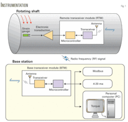
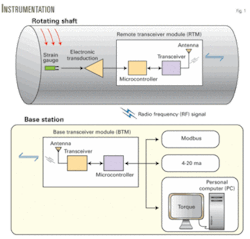
Fig. 1 diagrams the process. The electronic transduction circuit processes and amplifies the signal from the shaft deformation picked up by the strain gauge. The signal then goes to the remote transceiver module (RTM) where a microcontroller converts the analog signal to digital. The transceiver chip then modulates the signal in phase, phase shift keying (PSK), and excites the full duplex antenna, radiating the signal by radio frequency (RF).
The helical antenna in the base transceiver module (BTM) picks up the RF signal, which then is filtered through the transceiver chip (narrow-band filter), demodulated, amplified, and made available for reading.
One can access the measurements with a personal computer (PC), embedded or conventional, or make them available with the 4-20 ma standard (high immunity to noise) or Modbus protocol in industrial applications.
The system uses the shaft movement to generate the energy for the remote unit, which is in continual rotation.
Remote unit
Data acquisition starts in the remote unit with a strain gauge reading the deformation in the shaft. For a solid cross-section shaft of radius c, Equation 1 (see equation box) determines the torque.
To facilitate the processing the signal from the strain gauge, a Wheatstone bridge in the electronic transduction circuit generally converts the resistance to tension. For strain gauge circuit solutions, analog devices provide a synchronous demodulation and supply an ac signal to the Wheatstone bridge.12
Grupo de Pesquisa em Instrumentacao e Controle em Estudo de Energia e Meio Ambiente (GPICEEMA)—Group of Research in Instrumentation and Control in Energy and Environmental Study—developed a circuit with a concept different from the analog devices. Its circuit has similar performance with lower power consumption, greater integration, and lower cost.13
The signal conditioner circuit includes easily available components without needing instrumentation amplifiers as in References 14-17, without applying linearization techniques as in Reference 18, and with temperature autocompensation without adding a sensor element as in Reference 14.
For an 80° C. temperature, tests obtained a thermal drift of only 0.01%, an R-squared equal to 1, and a linearity error less than 0.07% of bottom of scale.
After adjustment of the circuit, Equation 2 calculates the torque.
In Equation 2, ΔVS is the variation of tension proportional to the resistance variation of the strain gauge caused by the torque.
For transmitting the signal from the transduction circuit of the remote unit (ΔVS), the system uses a radio frequency with a ZigBee communication protocol.19 The ZigBee was selected because of its viability for embedded applications that demand low energy consumption and its low cost. ZigBee sensors are important in the industrial sector.20 Among other factors, this is due to Zigbee technology having a low cost and supporting a large number of nodes, more than 65.000.21
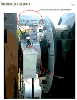
The remote unit set (strain gauge, electronic transduction, and RTM) has sensitive integrated-circuit technology. Because of its sensitivity to climatic conditions and the possibility of shaft rotation, GPICEEMA developed a clamp with a fiberglass flexible sealer for protecting and fixing this circuit. The clamps will not affect the measurements.
An electromechanical generator, developed by GPICEEMA, supplies power to the remote unit, eliminating the need for batteries and making the system energy self-sufficient.
The mechanical energy from the rotating shaft generates sufficient electricity for the remote unit. The electromechanical generator’s rotor has magnets of alternating polarity that provide an electromotive force (Equation 3).
The signal change of the electromotive force changes its polarity, stimulating an alternating electric current. This induced electromotive force complies with a harmonic law whose amplitude is given by Equation 4.
A rectifier changes the sine signal to a direct signal for the remote unit.
Fig. 2 shows the remote unit installed on a pumping unit.
Base unit
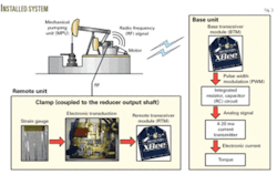
The base unit receives the torque signal from the remote unit and makes the signal available as standard 4-20 ma signal with one of the pulse width modulation (PWM) channels of the ZigBee module. A resistor connected to a capacitor in series (RC) integrator circuit converts the PWM signal from digital to analog and makes it available to the current transmitter.
The transmitter provides a practically noise-immune current, in the 4-20 ma standard, whose signal is integrated to the position of the position sensor on the pumping unit.
For studying the torque signal vs. crank position, LabView software provides concatenation of the signals transmitted from the output shaft of the reducer.
Fig. 3 illustrates the general system.
Lab tests
Torque calibration with all the mechanical variables verified is not practicable according to the state of the art; therefore, the torquemeter must be calibrated before installing it directly in the structure and estimating future dynamic behavior under the work conditions.22
To eliminate this limitation, tests aimed at a design that calibrated the torquemeter directly in the pumping unit, taking into account the dynamic variables of the system.
Two bench tests analyzed the system’s performance. One measured static torque for calibrating the telemetric dynamic torquemeter (batteries replaced the electromechanical generator). It evaluated the behavior of the devices in the remote unit. Another test simulated the torque due to the MPU’s counterweight.
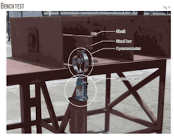
Fig. 4 shows the setup for testing the static torque with the steel bench, which is the material for the shaft of the reducer. The setup has a circular section shaft made of steel welded into one of the extremities of the bench. Near the end of the other extremity is a rigid transversal shank welded to the shaft.
To make the applied torque have pure shear tension, or worthless normal tension, the test used a shaft connected to a bearing made of three plates welded to the table. This eliminated the influence of torsion.
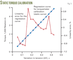
Through a metallic arm welded to the shaft, a hydraulic jack provided the torque to the shaft. A dynamometer obtained the torque in the metallic arm for input to LabView software. Fig. 5 illustrates the reference torque provided by the dynamometric ring and the signal sent by the remote unit, proceeding from the torque.
Table 1 relates the torque obtained through the reference instrument (dynamometric ring), the torque provided by the torquemeter idealized by this work (acquisition by LabView), and the error observed between them.
The data from Fig. 5 and Table 1 lead to a 0.54% (standard deviation of the errors) linearity error and less than a 0.3% bottom scale error between the torque value obtained through the dynamometric ring and the value transmitted from the remote unit to the base unit.
The prototype that simulates the torque due to the counterweight of an MPU consists of a 550-w engine, with rotational speed of 1,680 rpm connected to a reducer that provides an output rotation of about 15 rpm (equal to a size 912 MPU).
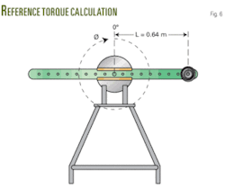
With the engine in motion, the disc turns a metallic arm that has reference weights in its extremity. The torque due to the reference weight complies with Equation 5 (Fig. 6).
In Equation 5, Tref is the reference torque due to the weight in the metallic arm extremity of the curve, P is the reference weight placed in the arm extremity, and θ is the rotation angle.
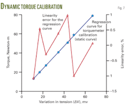
The tests obtained the calibration curve for the dynamic torquemeter (Fig. 7) from the relationship between the peak values of the electric tension sinusoids, provided by the torquemeter visualized by the LabView, and the reference torque obtained from Equation 5.
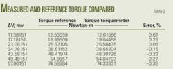
An analysis of the results from Fig. 8 and Table 2 of the torquemeter under dynamic behavior provides a 0.78% (standard deviation of the errors) linear error for low values of torque and less than a 0.7% maximum error of the measurements carried out regarding the reference torque provided by Equation 5.
Even with the vibration of the bench, the instrument uncertainty is 0.78% for the dynamic torque compared with the state of the art dynamic torquemeters whose uncertainty oscillates between 1 and 2%.23
Field tests
Field tests of the torquemeter verified the lab results. The tests took place from May 25 to June 25 in Carmopolis field, Sergipe state, in northeastern Brazil.
The data, stored on an embedded PC, indicate that the instrument did not have any problems during the test period. The torquemeter currently is still on the unit and continues to monitor the pumping unit’s torque.
The Petrobras (Petroleo Brasilerio SA) pumping unit (Fig. 8) is a model C-456D-305-144. It pumps from 700 m and produces 110 cu m/day of oil and water.
During the tests, two pairs of strain gauges glued in diametrically opposed axes provided measurements of the torque. The relationship between the two curves generated from the strain gauge measurements indicates efficiency of the calibration method.
Fig. 9 illustrates the two curves of the torque obtained. The curves have a 99.78% correlation coefficient and an average 1.251%.
The results show that torque obtained from the strain gauge detects even a vibration in the direction of the torque in the shaft, which the API method neglects.
The self-powered wireless torquemeter is efficient and generates low noise. Therefore, one can install this instrument in any rotation shaft.
Previously available torquemeters cannot be placed in pumping units because they are coupled through flanges or sockets, and torque calculations have about a 10% error for the best machine operating conditions.
Acknowledgments
The authors thank the National Council of Scientific & Technological Development (CNPq) for the financial support and also Petrobras for providing the pumping unit, supporting the visits to its facilities, and financial support.
References
- API, Specification for Pumping Unit, API SPEC 11E, 1994.
- Nascimento, J.M.A., “Simulador Computacional para Pocos de Petroleo com Metodo de Elevacao Artificial por Bombeio Mecanico,” Dissertacao de Mestrado em Engenharia Eletrica, PPGEE/UFRN, Natal, Brazil, 2005.
- Thomas, J.E., Fundamentos da Engenharia de Petroleo, Second Edition, 2004,
- Gibbs, S.G., “Computing Gearbox Torque and Motor Loading For Beam Pumping Units With Consideration of Inertia Effects,” JPT, September 1975, pp. 1,153-59.
- Keating, J.F., et al., “Lifting Cost Reduction form Dynamic Balancing.” Proceedings of 38th Annual Southwestern Petroleum Short Course, Lubbock, Tex., 1991, pp. 324-71.
- Gibbs, S.G., “Utility of motor speed measurements in pumping well analysis and control,” SPE Production Engineering, August 1987, pp. 199-208.
- McCoy, J.N., et al, “Motor Power/Current Measurement for Improving Rod Pump Efficiencies, SPE Production Operations Symposium,” SPE Paper No. 37499, Oklahoma City, Mar. 9-11, 1997.
- Durham, M.O., et al., “Comparison of NEMA and Ultra-High Slip Motors on Cyclic Loads,” Proceedings of Institute of Electrical and Electronic Engineers PCIC, PCIC-89-32, 89CH2777-1, San Diego, September 1989, pp. 91-96.
- Skinner, D.R., “Efficient Use of Electric Power in Production Operations,” Paper No. SPE 11559, JPT, August 1984, pp. 1,326-34.
- Ott, R., et al., “Reducing Electrical Consumption of Beam Pumping Units by Properly Counterbalancing Using PC Software, Southwestern Petroleum Short Course,” Lubbock, Tex., April 1995.
- Durham, M.O., “Beam Pump Motors: The Effect of Cyclical Loading on Optimal Sizing,” Paper No. SPE 18186, SPE ATCE, Houston, Oct. 2-5, 1988.
- Gerstenhaber, M., and Lee, S., “Application Note—Strain Gauge Measurement Using an AC Excitation Analog Devices,” NA-683, 2004.
- Lima Filho, A.C., “Torquimetro Dinamico Telemetrico Aplicado ao Eixo redutor de uma Unidade de Bombeio,” Dissertacao de mestrado, Universidade Federal da Paraíba, Brazil, Joao Pessoa-PB, 2007
- Ferrari, V., et al., “A conditioning circuit for resistive sensors combining frequency and duty-cycle modulation of the same output signal,” Measurement Science and Technology, No. 8, 1997, pp. 827-29.
- Munoz, D.R., et al., “Generalized Impedance Converter as a New Sensor Signal Conditioning Circuit,” Proceedings of Instrumentation and Measurement Technology Conference, Ottawa, 2005, pp. 17-19 .
- Svelto, C., et al., “Compact and accurate digital thermometer based on Anderson’s loop and Pt-100 sensor,” Measurement, No. 29, 2001, pp. 287-92.
- Anderson, K.F., “The New Current Loop: An Instrumentation and Measurement Circuit Topology,” IEEE Transactions on Instrumentation and Measurement, No. 46, 1997, pp. 1,061-67.
- Ghallab, Y.H., and Badawy, W., “A New Topology for a Current-Mode Wheatstone Bridge,” IEEE Transactions on Circuits and Systems-II: Express Briefs, No. 53, 2006, pp. 18-22.
- Baronti, P., et al., “Wireless sensor networks: A survey on the state of the art and the 802.15.4 and ZigBee standards,” Computer Communications, No. 30, 2007, pp. 1,655-95.
- Willig, A., “Recent and Emerging Topics in Wireless Industrial Communications: A Selection,” IEEE Transactions on Industrial Informatics, Vol., No. 2, 2008, pp. 102-23.
- Ciardiello, T., “Wireless communications for industrial control and monitoring,” Computing & Control Engineering Journal, Vol. 16, No. 2, 2005, pp. 12-13.
- Wegener, G., and Andrae, J., “Measurement Uncertainty of Torque Measurements with Rotating Torque Transducers in Power Test Stands,” Measurement, No. 40, 2006, pp. 803-10.
- Fujii, Y., et al., “A Proposal for a Dynamic-response-evaluation Method for Torque Transducers,” Measurement Science and Tecnology, No. 10, 1999, pp. 142-44.
The authors
Abel Cavalcante Lima Filho is pursuing a PhD at Federal University of Paraiba. His research interests include online monitoring of ac motors, telemetry, electronics transduction, and pumping unit torque. Lima Filho received an MS in mechanical engineering from the Federal University of Paraiba, Joao Pessoa, Brazil.
Francisco Antonio Belo is a professor at the Federal University of Paraiba. He has experience in the field of mechanical engineering with emphasis on transport phenomena. His research interests include multiphase flow, tomography, telemetry, and electronic transduction. Belo received an MS in mechanical engineering from Federal University of Paraíba and a PhD in mechanical engineering from the University of Campinas.
Ruan Delgado Gomes is a graduate student in computer science at Federal University of Paraíba. His interests in academic research are embedded systems, signal processing, and instrumentation.
