Desert project illustrates selecting acid-gas removal technology
Mahmoud Abu El Ela
Cairo University
Egypt
This article presents criteria that should be considered in preparing a short list of acid-gas removal processes that seem to be appropriate to meet treated-gas specifications. Final selection is on the basis of technical and economic criteria.
A case study for development of gas producing fields of 200 MMscfd illustrates the technology selection process. A CO2-removal system is required in the designed facilities to reduce the CO2 content in the produced gas to 3% from 7.2%. The amine system and the membrane technology are initially selected. The technical and economic evaluations show that the two-stage membrane system is the most appropriate technology for the project.
Such work is an original contribution to developing a methodology to select the best technology to remove acid gas from natural gas.
Natural gas usually contains acid gas impurities such as hydrogen sulfide (H2S) and carbon dioxide (CO2). It is usually desirable to remove these impurities to prevent corrosion and freezing at low temperatures and to increase the heating value of the gas.
In combination with water vapor, CO2 and H2S are highly corrosive and rapidly destroy pipelines and equipment unless they are partially removed or exotic and expensive construction materials are used. The specifications and the acceptable limits for these impurities in the pipeline sales gas are:1
• H2S maximum content: 6-7 mg/cu m; equivalent to 4 ppm (vol).
• CO2 content: 2-3 vol %.
Many processes are available for removing acid gases from natural gas, including chemical solvents, physical solvents, and membrane systems.2 Selecting among these processes depends on economic feasibility and cleanup ability. Solvent cost, equipment costs, and energy requirements for regeneration are the most important factors in selecting an appropriate process.3 4
Western Desert fields
A concession in Egypt's Western Desert consists of two oil fields and two gas fields. The production forecast shows that the estimated peak liquid hydrocarbon and gas production rates from the concession will be 19,000 b/d and 184 MMscfd, respectively.
For the development of these fields, an evacuation strategy has been performed to design central gas processing and oil treatment. The main objective of central gas processing is to provide minimum gas treatment.
Currently, the conceptual design and decision support package of the project have been prepared. The concession is about 155 miles south of El Alamein.
The gas-treatment plant mainly includes separation of the phases (gas, condensate, and water) and removal of the CO2 from the separated natural gas. Further treatment (dehydration and hydrocarbon dewpointing) for the separated gas is planned to be carried out at another, existing gas facility. Oil treatment is designed to stabilize the crude oil and condensate to achieve pipeline specifications. The liquid hydrocarbon is then pumped through the nearest pipeline for export.
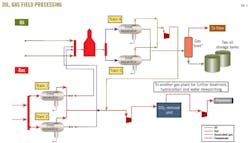
Design capacity of the gas and oil facilities is 200 MMscfd and 20,000 b/d, respectively. Fig. 1 presents a flow diagram for the oil and gas processing.
As shown there, the gas and oil streams are transported from each field to processing through a main flowline. Then, the oil and gas streams enter the main header upstream of the inlet separators of each oil and gas facility, each includes two parallel three-phase separators.
The operating pressure of the inlet separators of the oil treatment is 50 psia. The oil separated by the oil separators flows to a secondary separator (sometimes called a "gas boot") and then to storage tanks.
The associated gas separated from the oil facilities is compressed to 400 psi and transported into the gas facilities to be gathered with the nonassociated gas downstream of the inlet separators of the gas facilities.
The operating pressure of the inlet separators at the gas facilities is 400 psia. The separated condensate is transported into the inlet header of the oil facilities to be processed and stabilized with the crude oil. The separated gas (nonassociated gas) from the inlet separators is gathered with the associated gas from the oil facilities.
Available data show no presence of H2S in the gas; the CO2 content of the gathered gas, however, is about 7.2%. The gathered gas will be compressed and transported via an 80 km (about 50 miles) pipeline to another gas facility for dehydration and hydrocarbon dewpointing.
The presence of CO2 and water vapor in the gas can cause corrosion in the pipeline. Therefore, the gathered gas is compressed to about 1,100 psia and directed to the CO2-removal system to reduce the CO2 content to 3% before transportation.
Removal technologies
There are several processes for acid-gas removal. Among the most important are:
1. Reactive solvents: MEA (monoethanol amine), DEA (diethanol amine), DGA (diglycol amine), DIPA (di-isopropanol amine), MDEA (methyldiethanolamine), hot potassium carbonate, and mixed solvents.
2. Membrane systems.
3. Batch solid-bed absorption using iron sponge, molecular sieve, or zinc oxide.
4. Direct oxidation to sulfur: Stretford and Claus methods.
5. Physical solvents: Selexol, Recitisol, Purisol, and Fluor solvents.
There is no multipurpose process for acid-gas removal. Each case is specific and shall be studied accordingly. Final selection is on the basis of technical and economic criteria from a short list of processes that seem appropriate to satisfy the treated-gas specifications.
There are many factors and criteria to be considered in the selection of a given acid-gas removal process. The main factors include the following:5
1. Type of acid gas to be removed (CO2, H2S, mercaptans).
2. Acid gas concentrations in the inlet gas and the required specification of acid-gas concentration.
3. Gas flow rate.
4. Gas temperature and pressure.
5. Feasibility of sulfur recovery from the feed gas.
6. Presence of heavy hydrocarbons in the gas.
7. Relative economics of the project.
The existing project includes the following criteria:
1. CO2 is the only acid gas to be removed.
2. Concentration of CO2 in the gas is 7.2%. The required specification is 3%.
3. The gas flow rate is 200 MMscfd.
4. The gas temperature is 60º C. The gas is available at a pressure of 400 psi and can be compressed to 1,100 psi as the gas will be then transported to another location.
5. There is no concern for sulfur recovery in the current project.
6. There are heavier components in the gas upstream of the acid-gas removal system. The gas will be then transported into another plant for further water and hydrocarbon dewpointing.
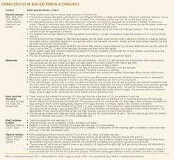
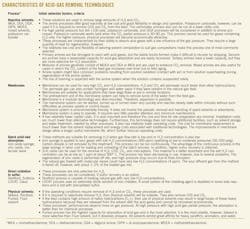
The accompanying box presents the characteristics of the acid-gas removal technologies. This box can be used to prepare a short list of acid-gas removal processes that seem to be appropriate to satisfy the treated-gas specifications. It indicates that the amine system and the membrane technology only are suitable for the existing project.
An amine process is selected because it is appropriate for feed gas of CO2 partial pressure less than 100 psia.5 The amine processes offer good reactivity at low cost and good flexibility in design and operation. In addition, these processes are characterized by their ability to absorb acid gas with a low influence of the gas pressure. However, they require a large heat quantity for regeneration.
Membrane technology is also suitable because it can be used for very high CO2 concentrations. CO2 will permeate much faster than other hydrocarbons. The permeate gas can also contain water vapor, which is suitable for the current project.
The pretreatment unit in the membrane system can also help to remove some of the water from the feed gas. It should be highlighted that the membranes increasingly are being selected for newer projects, especially for applications that have large flows or are in remote locations.
Batch solid-bed absorption methods are not considered because they are suitable if removal of H2S to very low concentrations is required. These methods are used when gas flow rate is low or H2S concentration in the feed gas is also low. Usually, CO2 is not removed by this treatment.
The methods of direct oxidation to sulfur are only selective for H2S. Therefore, these methods are not considered in the current project. They can be used if sulfur recovery is an option.
Physical solvent methods are also not suitable for this project because the feed contains high amounts of heavy hydrocarbons (C3+). The use of the physical solvents may result in a significant loss of these heavy hydrocarbons because they are released from the solvent with the acid gas and cannot be recovered economically.5 If it is required to remove H2S selectively, then physical solvents will be suitable. They also remove COS and CS2.
Membrane performance
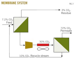
After communication with vendors, a two-stage membrane system was designed for this project. The two-stage system is better than a single-stage system for improving hydrocarbon recovery and reducing hydrocarbon losses. The proposed membrane system will treat feed gas and reduce CO2 content to 3% from 7.2%. Fig. 2 shows the configuration of the system.
The gas downstream of the inlet separator (associated and nonassociated gas) contains water vapor (H2O) and heavy hydrocarbons. This gas cannot enter directly to the membrane system because the water or heavy hydrocarbons might condense inside the membrane system and damage the membrane sheets. Liquids cause swelling of the membranes and destruction of membrane integrity. Therefore, it is recommended to install a pretreatment scheme upstream of the membrane system.
Based on the given feed composition, a standard pretreatment was selected to precede the membrane system. This pretreatment includes a filter coalescer, an adsorbent guard bed, a particle filter, and a preheater. The pretreatment unit has a major advantage in that it can help remove some of the water from the system and can also ensure that liquids will not form within the membranes themselves.
The systems are skid mounted units. Extensive testing with several suppliers has proven the enhanced pretreatment concept, and it is currently operating in different locations (OGJ, July 14, 2008, p. 68).
As shown in Fig. 2, the gas enters the first-stage membrane system, which selectively separates feed gas into a permeate stream rich in CO2 (30%) and a hydrocarbon-rich residue stream meeting the requested product gas CO2 specification of 3%. First-stage permeate gas is then recompressed.
After second-stage pretreatment (similar to first-stage pretreatment), gas will enter the second-stage membrane system, which selectively separates the second-stage feed gas into a permeate stream rich in CO2 (72%) and a hydrocarbon-rich residue stream, which will be recycled back to the first stage. Second-stage permeate stream will be flared.
The hydrocarbon recovery from such system is about 98.3%.
Amine performance
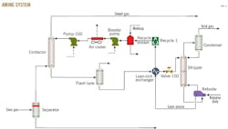
A 1,500-gpm amine system has been designed for the existing project (Fig. 3). The main equipment and criteria for the designed system includes the following:
• 108-in. ID amine contactor, flash tank, regeneration column, and reflux drum.
• Reboiler of a duty of 19.22 Mw, lean cooler, lean-rich heat exchanger, and reflux condenser.
• Two recirculation pumps of 820 kw each: one operating and one in standby. The recirculation rate is 1,500 gpm.
• Booster and reflux pumps.
• Full-flow charcoal filter.
• High-pressure treating skid including inlet filter coalescer, overhead scrubber, and a sweet-gas cooler.
Design of the amine process for the existing project can achieve performance similar to the membrane system. It can reduce the CO2 content to 3% from 7.2%. In addition, the amine processes are characterized by their ability to absorb acid gas with a low influence of the gas pressure. They require a large amount of heat for regeneration.
The use of blended amines in gas treating can improve the absorption capacity, absorption rate, and also savings in solvent regeneration energy requirements (OGJ, Feb. 7, 1983, p. 55).6-8 This approach could dramatically reduce capital and operating costs, while providing more flexibility in achieving specific purity requirements.
Selecting technology
Membrane system seems to be the most appropriate CO2 removal technology for the existing project for many technical and economic reasons, including:
• Membrane systems can remove some of the water vapor in the pretreatment unit. The treated gas with the amine system will include high water content that will affect the pipeline downstream of the treating.
• Membrane systems involve minimal utility requirements. The amine-based technology, however, requires much larger quantities of power, process water, cooling water, and steam.
In the amine system, pure water is required to dilute the solvent. In addition, heating is required for solvent storage. Moreover, the exothermal chemical reaction requires a large amount of energy for regeneration (to extract acid gas from the solution).
• Membrane is a skid-mounted system, which is quick, easy, and inexpensive to install.
• Membrane is a modular technology. Therefore, expansion is possible in case of future increased throughputs or increased acid-gas removal requirements, and delivery and construction are faster with no large columns called for. In addition, the membrane system can be started up, turned up, or turned down within minutes and reaches steady-state conditions within minutes without such difficulties as process upsets or control issues.
• The membrane systems are well suited to handling fluctuating feed conditions over the life of the unit. A variable removal rate is possible by simply adjusting the membrane system's operating parameters (e.g., permeate back pressure) or by isolating sections of the available membrane area (OGJ, July 14, 2008, p. 68).
• The membrane system is environmentally friendly. It does not involve periodic removal and handling of spent solvents or adsorbents. Permeate gases can be flared, used as fuel, or reinjected into the reservoir (OGJ, Jan. 7, 2013, p. 74). In addition, items that need disposal, such as spent membrane elements, can be incinerated.
• With the membrane system, there is no corrosion linked to the use of solvents. Amine system might face corrosion resulting from solution oxidation (contact with air) or from solution superheating during regeneration of the amine system.
• The membrane system does not involve foaming, but the risk of foaming is expected with the amine system when the solution contains suspended solids.
• The membrane system is easy to operate, requiring little operator attention and minimum maintenance.
• The budgetary estimate for the designed two-stage membrane system is €11 million (about $14.8 million). The budgetary cost estimate for the 1,500-gpm amine plant, however, is $11 million.
For a given economic analysis, choosing a process with low initial installation cost might not be the best option since the operating cost may be high, making the breakeven point unattainable. Generally, the amine system has a lower capital cost than the membrane system, but the operating cost of the amine system is much higher than for membrane technology due to the heating requirements in the regeneration package.
The only major operating cost for membrane systems is membrane replacement. This cost is much lower than the solvent replacement and energy costs associated with amine system. The improvements in membrane and pretreatment design allow a longer useful membrane life, which further reduces operating costs.
Therefore, the membrane system was selected for the existing project.
References
1. Engineering Data Book, 13th ed., Tulsa: Gas Processors Suppliers Association, 2012.
2. Kohl, A., and Nielsen, R., Gas Purification, 5th ed., Houston: Gulf Publishing Co., 1997.
3. Ebenezer, S., and Gudmundson, J.S., "Removal of Carbon Dioxide from Natural Gas for LNG Production," Technical Project Work, Institute of Petroleum Technology Norwegian, Trondheim: University of Science and Technology, 2005.
4. Siu-Ming YiH and Hung-Cherh Lai, "Simultaneous Absorption of Carbon Dioxide and Hydrogen Sulfide in a Packed Absorber-Stripper Unit," Chem. Eng. Comm., Vol. 51, pp. 277-290, 1986.
5. Hussein, K., Abdel-Aal, Mohammed Aggour, and Fahim, Mohamed A., Petroleum and Gas Field Processing, New York: Marcel Dekker Inc., 2003.
6. Lallemand, F., and Minkkinen, A., "Highly Sour Gas Processing in a More Sustainable World," in Sustainable Industrial Chemistry, eds. Fabrizio Cavani, Gabriele Centi, Siglinda Perathoner, and Ferruccio Trifiró; Hoboken, NJ: John Wiley & Sons Inc., 2009.
7. Mandal, B., and Shyamalendu, S.B., "Simultaneous Absorption of CO2 and H2S into Aqueous Blends of N-Methyldiethanolamine and Diethanolamine,"Environmental Science & Technology, No. 40 (2006), pp. 6076-6084.
8. Polasek, John C., and Iglesias-Silva, Gustavo A., "Using Mixed Amines Solutions for Gas Sweetening," presented to the 71st Annual Gas Processors Association Convention, Anaheim, Calif., Mar. 16-18, 1992.
The author
Mahmoud Abu El Ela ([email protected]) is an associate professor in the petroleum engineering department, Cairo University, and an associate professor in the university's Petroleum and Petrochemicals Engineering Consultants Group (PPEC Group). He is also a manager of projects (acting) at WorleyParsons Engineers Egypt Ltd. Previously he was a lead process engineer at WorleyParsons, assistant professor in the petroleum engineering department at Cairo University, petroleum process consulting engineer for Khalda Petroleum Co., and a research engineer at Woodside Research Foundation (Curtin University of Technology, Australia). Since 1997, he has been a technical consultant in petroleum engineering for national and international companies. He holds a BSc and MSc in petroleum engineering from Cairo University and a PhD from Curtin University.
