ESP pump selection, evaluation improve well inflow, volumes
Kevin P. McCoy
Warren E&P Inc.
Long Beach, California
Variable-frequency drives (VFDs), allow a much wider operating range on selected electric submersible pump (ESP) equipment than might otherwise be possible. This can be beneficial when an ESP is installed in a new well where the production range is uncertain.
While a pumpjack-operated well is complex and requires massive equipment, the daily volume of oil or fluids produced from the well can be easily calculated. Conversely, an electric submersible pump (ESP) is a simple device, but its behavior is complex because production volumes are a function of rotational speed and fluid head.
This article provides guidelines for how to design and size an ESP for new wells, removing some complexity and the misperceptions that can accompany it. The article is based on Warren E&P Inc.'s experiences in its California wells. It is not intended to address very high viscosity wells, high gas-oil-ratio (GOR) production, or high temperature-ultra deep wells.
ESP Systems
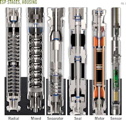
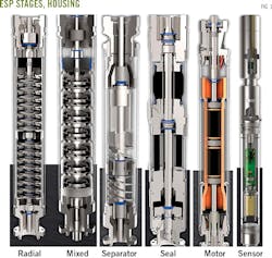
Fig. 1 shows an ESP system with a discharge head, pump, intake, seal assembly, a motor connected to the pump by a long shaft, and a downhole sensor.
The discharge head connects the equipment to tubing giving produced fluids a conduit to the surface. A pressure line from the discharge head to the downhole sensor enables discharge-pressure measurement.
Each pump stage is formed by combining an impeller and a diffuser with the matched rotating impeller keyed to the pump shaft. This creates the lifting force or "head."
The diffuser directs fluid to the next impeller and does not rotate. Pump efficiency and head generation is a function of the diameter of the impeller and the rate of rotation. The smaller the diameter of the impeller, the less head generated, which results in more stages and longer pumps to raise fluid from the reservoir to the surface.
California operators typically use ESPs designed for about 100-5,000 barrels of fluid per day (bf/d). Pump stages can be classified as either radial, mixed, or hybrid flow. Produced fluids usually have entrained gas. While the GOR may be 80-500 scf/bbl, the gas-liquid ratio may only be 20-30 scf/bbl. Oil produced by ESP can be 8-18° API.
Radial, mixed-stage
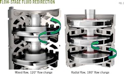
Fig. 2 illustrates both mixed and radial-flow stages. Radial stages are efficient but do not handle gas or solids well. Radial-flow staged pumps can be run in more benign wells with known flow ranges, no scale, and limited sand or low-gas content.
Fluid in a radial design is flung outward to the edge of the stage and then redirected 180° back to the center. From the center, the fluid moves upward into the next stage, and then repeats the cycle.
If solids are present in the fluid, they tend to be directed against the diffuser wall during redirection and against the central shaft following the 180° change, resulting in severe erosion. This problem worsens as the amount of sand or other solids increases.
Radial stages tend to have a very thin vertical section. The clearance between the impeller and diffuser is small. Solids separation occurs via fluid dynamics, sand grains tending to drop out and plug the impeller due to restricted flow from the diffuser inward. Scale deposits that break loose can also damage a radial stage and result in plugging.
Mixed-flow stages can handle higher gas-fluid ratio wells and fine particulates better, offering a wider range of operation than radial-type stages.
Warren has had mixed-flow ESPs handle up to 10% sand with the equipment still running after 24 months. In such cases the pump was simply moved upward out of the moving sand instead of cleaning the wellbore. Mixed flow stages tend not to redirect fluid and solids as drastically as radial flow and there is less erosion.
Under most circumstances, the lower the solids content of the fluid, the longer the equipment will run. Warren has 17 ESPs that have been in operation for more than 84 months.
Warren recently replaced many long-lived ESPs, largely due to corrosion of either the motor (the anode ceased to function) or holes in the tubing string. Larger anodes, internally coated tubing from top to bottom, and chemical capillary tubes set to discharge at the anode, alleviate this issue.
Below the pump is an intake that allows fluids (gas, water, and oil) to enter. Separation of some of the gas may occur through a static rotor system or a dynamic rotor system that imparts a velocity to the stream. Fluids are spun, the gas is stripped off from the center, and the fluids move to the outside of the device to enter the pump.
Below the intake is a seal or protector system. The seals enable expansion or contraction of oil in the motor, and isolate the oil from the wellbore. Seals are commonly referred to as bags or labyrinths. Bags typically are used for horizontal wells and labyrinths for vertical wells.
Below the seals is an asynchronous motor. Warren usually runs derated motors that can handle higher momentary electrical currents, resulting in longer run lives and longer times between workovers. Its additional horsepower is useful during startups when solids have settled in the ESP's upper stages.
Below the ESP's gauge package is an anode designed to dispense chemicals for corrosion control or emulsion control.
Warren typically powers the ESP with a No. 4 AWG round cable, which is more than adequate for installations up to 175 HP. Wellbore clearance is sufficient to allow passage of the cable, and its round shape easily joins to the pass-through mandrels used in the tubing hangar. Only tight-clearance liners require a flat cable, which is then changed to round in the intermediate casing for cost savings.
A 1⁄4 or 3⁄8-in. chemical line runs beside the power cable to a specially designed anode where chemicals are dispensed through a one-way check valve inside the anode that prevents high-pressure reservoir fluids from flowing up the chemical line.
Warren uses plug-in-style connections at the surface through the tubing hangar, ensuring isolation of wellbore fluids from the atmosphere while enabling a quick connect-disconnect feature. The motor and cable can also be tested when the tubing hangar is landed and the blowout preventer stack is still on the well, potentially saving time and money.
ESPs are powered from the surface and can be run across the line with soft starts or using variable speed drives (VSDs). An across-the-line configuration is less expensive, but the pump will only have one speed. Changes in fluid inflow may require the installation of a choke at surface or recycling of fluids to prevent pumping the well dry. The high influx current can also be damaging to the downhole equipment.
Soft starts help initiate production, but once a well is running, the ESP is limited to 60 hz. VSDs allow soft starts while at the same time accounting for changes in reservoir pressure and fluid inflow.
VSD's noise, however, can result in data transmission and harmonics problems. Their imperfect sine wave can also lead to cable-insulation stress and hazardous peak voltages. Warren works with service companies to design equipment that operates at a typical frequency of 48 Hz, resulting in ESP run times exceeding 84 months on many wells and generally reaching 60-72 months.
Pump design
Warren uses three standardized pump designs. The first is for tar formations found at 2,600-2,700 ft total vertical depth (TVD). The best solution for these formations is a pancake-radial pump, however, the thick initial production of oil-water emulsion precludes running the more efficient pump. A mixed-flow pump, therefore, is installed even though, later, water will become the predominant phase.
The Ranger and Upper Terminal formations, from 3,000-3,600 ft TVD, typically use a mixed flow pump because of the wide range of gross-fluid production and the production of fine particulates. Production is as much as 3,500 bf/d from horizontal wells 250 ft apart, depending on formation characteristics and injection support.
The Ford formation uses a pancake stage and is set at mid-perforation, or about 300 ft into the formation at 5,000 ft TVD.
Radials are typically used for gross fluid rates less than 1,000 bf/d that have more water than highly viscous crude and little to no thick emulsions.
Warren uses mixed-flow stages for higher flow rate wells. They are effective in the tar formation despite the resulting inefficiency. Mixed-flow stages handle solids much more efficiently than radial stages, with less plugging and wear.
Warren employs VFDs on all ESP installations. The drive increases flexibility and optimizes fluid-over-the-pump and pump rates, allowing a mean time-to-failure of more than 84 months.
Applications
Examples of real-world circumstances and their effect on design include:
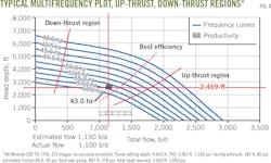
• Example 1. An operator was starting production on a new Monterey, Calif., well. Tank measurements showed inconsistent production volumes. The pump was running at 43 hz and the fluid over the pump was 376 psi. The site typically ran at 80 psi, with estimated friction of 30 psi. The pump was set at 4,635 ft maximum depth (MD), or 3,062 ft TVD. A fluid column of that height exerts 1,359 psi of downward pressure. The required head the pump had to overcome, therefore, was 1,359 + 80 + 30 - 376 psi = 1,093 psi, or 2,469 ft of head.
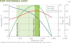
Fig. 4 demonstrates how to determine the volume produced by the ESP in these conditions. Draw a line across the graph at 2,469 ft. Interpolate 42.5-45.0 hz by drawing a line perpendicular to a tangent on the 42.5 hz curve.
PowerPoint software can create a bar to position sideways for fluid interpolation or perpendicular to the blue lines for frequency interpolation.
Estimated pump production was 1,130 bf/d. The well's actual production equaled 1,100 bf/d. The test was accurate.
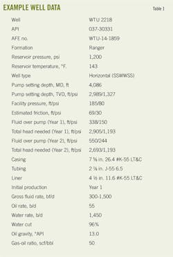
• Example 2. Four pump suppliers received the same information regarding the WTU 2218 well in the Ranger formation (Table 1). The pump was to be set at 4,086 ft MD or 2,989 ft TVD (hole angle >80°) and needed to handle 300-1,500 bf/d, comprised of 9-57 b/d oil and 214-1,195 b/d water.
Fluid over the pump was designed for 150 psi, which included back pressure of 80 psi and estimated friction of 30 psi. The total head required to lift fluid from the reservoir was 2,905 ft or 1,287 psi.
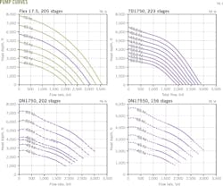
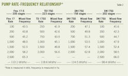
Fig. 5 shows the four different pump curves provided by the suppliers. The rates and frequencies for each of the pumps were derived following the process outlined in Example 1 (Table 2). Warren prefers to start pumps at 42 hz, let the gravel pack build and then run the pump at 48 hz. The slower the pump turns, the less wear-and-tear on the equipment and the longer the life.
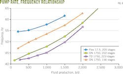
The barrels of fluid moved for each hz change should be reasonably constant and not flat to control fluid production. The proposed gear is matched with pumps operating at about 100-120 bf/d/hz change (Table 2).
Fig. 6 plots Table 2 data. The Flex 17-5 pump starts higher than Warren's normal operating conditions and only reaches the desired rate of 1,500 bf/d.
The DN1750 158-stage pump runs at 53 hz for 1,000 bf/d. The DN1750 202-stage and the TD1750 223-stage pumps have similar characteristics. The TD1750 is a little flatter in the lower rates, making it marginally harder to control if the drive software can't tolerate changes of 0.1 hz or less. Both 200+-stage pumps could be used.
Maximum horsepower
A third example illustrates how to determine maximum horsepower needed to achieve optimal flow.
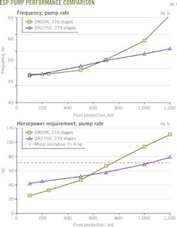
• Example 3. A supplier had the option of running a pump in a well with potential production of 100-800 bf/d. The curves for two different pump types were analyzed and plotted.
Fig. 7 shows how each pump performed relative to frequency. The first frequency-rate plot shows how sensitive an ESP pumping rate is to frequency changes. The 279-stage pump is too difficult to control, with greater potential fluid-volume changes at smaller frequency changes.
The second HP-rate plot shows the horsepower required at any given rate and the frequency associated with that horsepower. If the pump is limited by horsepower constraints (as it was in this design) the maximum fluid rate becomes apparent and redesign might be called for.
Acknowledgments
The authors wish to acknowledge the contributions of Ellis G. Vickers, Warren Resources Inc., and Peter Hege, Luis Moncada, and Braidon Waggoner, GE Oil & Gas Artificial Lift.
The authors
Kevin P. McCoy ([email protected]) is the petroleum engineering manager for Warren E&P Inc.'s California fields. Prior to joining Warren, he held positions with several international companies in operational, development, and management roles. McCoy holds a BS in mechanical engineering from the University of Manitoba, Winnipeg.
Michael Anderson ([email protected]) is a senior area leader for GE Oil & Gas Artificial Lift. He has been in the industry for more than 34 years. Anderson is pursuing a degree from Arizona State University, Phoenix, in business management and business communications.
