Chevron Anchor pioneers 20K subsea development
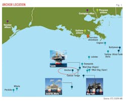
Anchor field lies offshore Gulf of Mexico (GOM) in Green Canyon, about 140 miles off the Louisiana coast in about 5,000 ft of water (Fig. 1). The field is the first deepwater high-pressure high-temperature (HPHT) development with equipment able to withstand pressures of 20,000 psi (20K).
Anchor Phase 1 development will consist of seven subsea wells tied into a semi-submersible floating production unit (FPU) with 75,000 bo/d and 28 MMscfd capacity. The field contains an estimated 440 million boe total potential recoverable resources. Chevron Corp. is operator at Anchor and holds 62.86% working interest with partner TotalEnergies E&P USA Inc. holding the remaining 37.14%. Chevron started production from the first Anchor well in August 2024.
Anchor 20K decision
Anchor produces from reservoirs in the Lower Tertiary Trend at 30,000-34,000 ft TVD with 23,000-27,000 psi initial bottom-hole pressure. Maximum anticipated wellhead pressure (MAWP) requires equipment rated to 17,000 psi, clearing the 15,000-psi HPHT threshold. The 275° F. maximum flowing tubing pressure, however, falls below the 350° F. HPHT temperature threshold.
Chevron decided to develop a full 20K system to prepare for future projects which will experience 20,000 psi subsea maximum shut-in pressures and to further develop American Petroleum Institute (API) and Bureau of Safety and Environmental Enforcement (BSSE) HPHT governing standards. Anchor also provided a significant market for OEMs to justify developing 20K equipment. Chevron’s development costs were shared across other operators.
This approach resulted in complicated intellectual property (IP) concerns. Each vendor contract for 20K technology and equipment tackled unique IP issues. These contracts addressed ownership of IP, test data, and independent third party (I3P) reports required for regulatory qualification. Chevron coordinated information exchange between vendors, I3P reviewers, and regulators. Chevron ultimately recovered much of its 20K technology development investment through data-sharing transactions based on a cost recovery rather than for-profit model.
HPHT drilling, completion, and intervention equipment qualification proceeded per BSEE’s HPHT guidelines in its Notice to Lessees and Operators (NTL) No. 2019-G02 and No. 2019-G03. These NTLs apply the Code of Federal Regulations 30 CFR Part 250 for HPHT developments. NTLs provide voluntary submissions for operators to provide BSEE documentation for review earlier in the approval process than required by regulations. They also provide guidance on I3P reports and content requirements for equipment and well design. BSEE provided guidance for well control by specifying required and redundant mechanical barriers and outlining pressure containing and controlling elements.
Anchor development
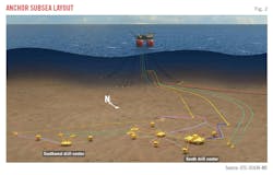
The Anchor subsea development consists of seven wells, with two production drill centers tied back to an FPU. Fig. 2 shows the South Drill Center (SDC) and Southwest Drill Center (SWDC) which allow sufficient well penetrations through the reservoir.
Long step-outs, deepset heavy casing strings, and MAWP exceeding 15,000 psi required construction of the Transocean Deepwater Titan drillship with a 20,000-psi blowout preventer (BOP) and 3-million lb hookload-capacity. Even with this increased hookload beyond the standard 2.5-million lb drillship capacity, the Wilcox sand depths dictated minimal directional drilling and step-out to stay within drillship capacity.
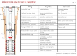
Well design analysis produced functional requirements for 20K Anchor well service. Fig. 3 lists the 20K equipment required for Anchor. API HPHT standards and practices leave room for interpretation of qualifications for this equipment, and stakeholder subject matter experts (SMEs) did not agree on all interpretations of the standards. Frequency effect on fatigue life, based on API 17TR8 guidance, provided a major example of differing opinions.
Pressure cycle-induced fatigue at 20K plays a large role in determining overall component fatigue life. Fatigue does not increase linearly with pressure, rendering lower-pressure fatigue data inadequate. API 17TR8 design verification uses Woehler curve plots of stress (S) vs. number of cycles to failure (N) in small-scale samples to estimate fatigue life for critical 20K equipment, with adjustments based on field in-service pressure cycles applied to the component. S-N curve-derived fatigue life does not undergo environmental correction because the small-scale samples are tested in a range of field environments.
API 17TR8 Edition 2 bases S-N frequency testing on environmental loadings (e.g., wave action) which includes frequencies of ≤ 10 hz in air and ≤ 0.3 hz in environment. It allows for higher or lower frequencies based on design criteria, but these selected frequencies have historically been the dominant driver of fatigue.
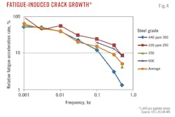
For the Anchor 20K subsea application, however, applied pressure cycles rather than environmental loadings dominated fatigue life. Well and equipment pressure tests typically held for 15 minutes resulted in an applied frequency of about 0.001 hz. Offshore structure and pipeline tests indicated that accumulated fatigue from low-frequency events may be greater than from higher frequency events under the same applied load. Fig. 4 shows how fatigue crack growth rate decreased as a function of stress-loading frequency in a range of pre-cracked metallurgical specimens undergoing constant stress intensity.
To account for low-frequency events, frequency scan testing on pressure-load cycle fatigue sensitive equipment produces downward adjusted (knockdown) factors to the S-N curves generated at the standard API 17TR8 10 hz or 0.3 hz frequencies. This approach may produce overly conservative fatigue-life estimates which could lead to premature replacement because, unlike inspection-based service life estimates, S-N curve-derived fatigue life cannot be adjusted while in service based on inspection. Once the theoretical fatigue life is reached, the equipment is removed and replaced regardless of condition.
Chevron’s service life estimates for subsea components exposed to regular periodic pressure testing included both non-frequency-adjusted and frequency-adjusted fatigue to outline less conservative to more conservative ranges of fatigue life, respectively. For the initial phase of the Anchor project, Chevron chose to use the more conservative knockdown, frequency-adjusted fatigue life estimates.
API 17TR8 specifies a 10x safety factor for non-inspectable equipment. Chevron adopted this safety factor for all Anchor equipment but expects to apply more accurate life and safety factors after obtaining sufficient 20K production experience. Revised safety factors will especially apply to completion equipment, where the criticality of the component, failure modes other than fatigue, estimated service life relative to expected well life, and the ability of the equipment to be safely and economically replaced via workover will be considered.
Full-scale test validations were performed on a few high-strength components under field loading conditions and frequency. Unlike S-N curve analysis, full-scale validation testing results in fatigue management through inspection. These tests were conducted on 4340 steel in BOP and completion workover riser shear ram blades. S-N testing of this material usually results in significantly lower fatigue life than experienced in the field.
Anchor drilling campaign
The Anchor exploratory and appraisal well campaign evaluated Anchor reservoirs containing Eocene and Paleocene turbidites which have lower permeability than common producing GOM Miocene strata. Paleocene sediments are in the Wilcox formation, which ranges in depth from 30,000 ft TVD at the crest of the Wilcox 1 reservoir to 34,000 ft TVD at the base of the Wilcox 4 reservoir.
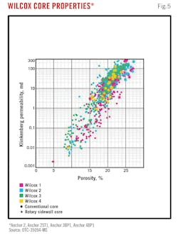
Appraisals included logging-while-drilling, pressure and fluid sampling on wireline, and coring. The deepwater Wilcox contains fine and very fine-grained sandstones, siltstones, and interbedded shales. Anchor Wilcox reservoirs contain thick pay columns, relatively high net-to-gross ratio, high porosity, and high permeability compared with other Wilcox reservoirs. Permeability-porosity relationships show a positive trend with 100-300 md permeability for cores with 22-27% porosity, respectively (Fig. 5).
Before Deepwater Titan was available, development wells AP001 and AP002 were predrilled with an existing 2.5-million lb hookload drillship. Simple trajectories minimized hookload from the 16-in. liner. Additional operational precautions included a heavy-duty landing string to run the liner to target depth, upgraded shear-and-seal capability of the blind shear ram, a buoyed landing string (BLS) to minimize hookload, and increased inspection and QA/QC.
The BLS produced a hookload reduction of about 160,000 lbf while running the 16-in. liner, resulting in the rig safely running and cementing the liner on depth. The rig recorded a hookload of 2.494 million lbf, near rig capacity, showing the importance of the BLS and other hookload reduction and safety measures applied for drilling these wells. The Deepwater Conqueror drilled and temporarily abandoned both wells for completion upon arrival of the Deepwater Titan.
For drilling the additional wells and performing the completions, the Deepwater Titan ran two 20K BOP stacks and a lower marine riser package (LMRP) between the stacks weighing a combined 131,600 lb. The lower BOP incorporated three double ram units, the upper BOP contained a double unit with two blind shear rams, and the middle and lower doubles have four rams with cavities available for various rams for flexibility while running completions. Weight and height drove the bending moment and resultant fatigue life of the wellhead. A single 10,000-psi annular preventer in the LMRP reduced this moment and offset the increased weight of ram bodies and pressure-containing components in the 20K BOPs.
The BOP incorporated a load monitoring system to record fatigue life. Two HPHT sensors on the choke and kill lines and two HPHT sensors under the middle pipe ram and test rams monitored applied pressure. Environmental loads were captured using two load collars under the flex joint and lower double ram.
The two Anchor appraisal wells experienced extrusion of the second position casing hanger through the wellhead when non-20K rated wellheads were used on Deepwater Conqueror. This intrusion was the result of high string loads combined with potential wellbore debris at the hanger. To address this issue, Chevron qualified a 20K wellhead, designated the SS-20 BigBore IIe, for subsequent Anchor service.
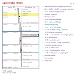
The system consists of a low-pressure housing with 36-in. OD, 2-in. thick conductor. A high-pressure housing was locked into the low-pressure housing and contains a first position casing hanger for a 14-in. intermediate casing string and a second position hanger for the 11 ¾- in. tieback string. A lockdown sleeve prevents discharge from the tieback seal assembly in case of a well event that exceeds the seal assembly's lockdown capability.
Anchor completions required an industry first 20K API 17G-qualified completion landing string which included a hybrid spanner joint assembly (HSJA). The HSJA contained a direct hydraulics-controlled spanner joint, and a ball valve assembly rated to shear and seal wireline strings. This design added a safety barrier for wireline intervention and backed up the isolation valves in case of failure. Intervention only required wireline-deployed mechanical shifters rather than mobilizing another 20K intervention package.
20K wireline tools and coiled tubing were developed for Anchor bottom-hole conditions. Wireline tool operating requirements included 28,500-psi minimum working pressure and 350° F. working temperature.
Coiled tubing provided fluid circulation and proppant transport efficiency during fracture cleanout operations at 35,000-ft MD with concurrent mechanical strength and bend cycle fatigue requirements. A string was not commercially available, requiring development of an Anchor-specific string with 145,000-psi yield strength material, 20-in. OD, 0.156-0.250-in. tapered WT, and 36,500-ft length. The string can withstand 14,500-psi collapse load based on Anchor’s MAWP. The resulting 20-ft reel required special ground transport frame, routes, and permits.
Anchor well design
Anchor wells contain 11.25-in. production tie-back casing, 10.25-in. upper production liner, and 10.05-in. lower production liner (Fig. 6). The large production casing across the reservoir optimized inflow performance and fracture stimulation hydraulics. The casing OD provided clearance while providing high-load design factors. The production tieback has a 9.25-in. drift and both liners have 8.50-in. drifts for control line clearance. The tieback casing and upper production liner contained low alloy steel designed for mild sour service with 130-ksi minimal yield strength. There were no requirements for sour service for the lower production casing.
Anchor production required vacuum insulated tubing (VIT). An enhanced VIT comprising two 15Cr tubulars produced tubing with 6.08-in. OD, 4.50-in. ID, and 135-ksi yield strength. The design mitigated annular pressure buildup weakness. The tubulars were welded together with a connection threaded onto the outer tubular. The internal pressure rating is governed by the 4.50-in. inner tubular, and the connection pressure rating was validated to that of the inner tubular.
Anchor completions
Anchor Stage 1 wells produce by primary depletion. Flowing bottom-hole pressure is to remain above bubble-point pressure, eliminating gas breakout in the reservoir. Anchor wells completions are in Wilcox 1-3 or Wilcox 1-4 zones using single trip, multiple zone fracpacks for reservoir stimulation and sand control. Production is commingled in all zones as Wilcox 1-3 zones lie on a common pressure gradient, and fluids are compatible across all zones. Expected field life is 30 years.
The first two Anchor predrills (AP001 and AP002) were completed with fracpacks. The wells encountered Wilcox 1-3 zones with combined 809-ft (AP001) and 850-ft (AP002) net thickness with good properties. AP001 contained six fracture treatments and AP002 contained five fracture treatments.
Bibliography
- Chase, T., Garcia A., Marchman, K., Mendoza, M., Eberstein, C., Tritz, J., Tritz, N., Jordan, C., and Smith, L., “Designing and Qualifying Equipment for a Potential World-Record Deepwater Casing Landing Operation,” IADC/SPE-212545-MS, SPE/IADC International Drilling Conference and Exhibition, Stavanger, Norway, Mar. 7-9, 2023.
- Falcon, R., Braun, C., Klaus, K., Shinde, S., Wu, G., and Rodriguez, I., “Anchor Project: Best Practices and Lessons from Detailed Design Through Fabrication of the Anchor FPU,” OTC-35076-MS, Offshore Technology Conference, Houston, Tex., May 6-9, 2024.
- Kusinski, G. and Kaculi, J., “Anchor Project: 20K Regulatory Process and Approval – Challenges and Lessons Learned,” OTC-35036-MS, Offshore Technology Conference, Houston, Tex., May 6-9, 2024.
- Ogden, K., Bordenave, T., and Luo, Y., “Anchor Project: The Subsurface Journey from Discovery to Development,” OTC-35094-MS, Offshore Technology Conference, Houston, Tex., May 6-9, 2024.
- Reiners, J.M., Cheatham, B., Dampman, A., Gaudet, K., and Nakhle, F., “Anchor Project: Best Practices and Lessons from Delivering the Offshore Installation Scope,” OTC-35303-MS, Offshore Technology Conference, Houston, Tex., May 6-9, 2024.
- Ross A.J. and R. Ramirez, R., “Anchor Project: Lessons and Challenges From Developing 20K Rated Wells Equipment,” OTC-35148-MS, Offshore Technology Conference, Houston, Tex., May 6-9, 2024.
- Sauer, S., White, R.D., and Varnado, M., “Anchor Project: Processes, Lessons and Challenges from Developing 20K Subsea Equipment,” OTC-35256-MS, Offshore Technology Conference, Houston, Tex., May 6-9, 2024.
- Stamper, S., Chase, T., Lanceslin, D., and Ugah. I., “Anchor Project: Development Planning Approach for Drilling, Completion, and Intervention on 20K Wells,” OTC-35436-MS, Offshore Technology Conference, Houston, Tex., May 6-9, 2024.
About the Author
Alex Procyk
Upstream Editor
Alex Procyk is Upstream Editor at Oil & Gas Journal. He has also served as a principal technical professional at Halliburton and as a completion engineer at ConocoPhillips. He holds a BS in chemistry (1987) from Kent State University and a PhD in chemistry (1992) from Carnegie Mellon University. He is a member of the Society of Petroleum Engineers (SPE).
