SPECIAL REPORT: All-electric actuated subsea system qualified, implemented
After about 8 years of design, testing, and qualifying, the all-electric actuated subsea system is now ready for is first commercial installation on gas wells off the Netherlands.
The benefits of the all-electric system compared with hydraulically actuated systems include improved reliability, availability, and enhanced functionality and performance of subsea controls.
The system also eliminates the environmental concerns of venting or the leakage of control fluids to the sea. Coupled with savings in high-cost control fluids and equipment, the all-electric system offers operators a cleaner, more economical alternative to hydraulic-based systems.
The all-electric system can also facilitate control of ultralong distance offset wells, subsea-to-beach installations, and complementary technologies such as subsea separation and processing.
System design
Cameron, perceiving the trend in subsea completions toward increased step-outs and water depths, recognized the limitations of electrohydraulic control and initiated work on an all-electric system in 1999. From the earliest conceptual design stages, it considered such requirements as increased reliability, availability, maintainability, cost savings, standard equipment interface and footprint, low power consumption, ease of use, and simplified hardware.
As an unintended bonus, complete removal of hydraulic fluid makes the all-electric system environmentally friendly as well.
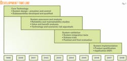
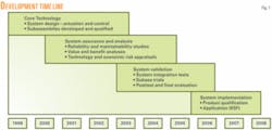
The time line in Fig. 1 provides an overview of the development, testing, and implementation program. Note that early in development several analyses assessed the robustness and economic viability of the design, and the results of these studies led to updated design parameters and modifications. The first years of the program established several fundamental design criteria.
To overcome long-distance power transmission problems, the program selected DC power. It can facilitate step-out distances beyond 400 miles with high transmission efficiency.
For communications, the current system uses a coaxial cable at a 19 kbit/sec data rate. In the future, fiber optics will provide greater bandwidth and allow longer step-outs.
The most reliable means of storing energy for the fail-safe gate-valve actuators is by compressing a large spring and, because of this, the design maintains this technology. With the energy stored in the springs, batteries and the troublesome battery connections and cabling become unnecessary, making the system fail-safe.
Two high-torque brushless DC motors drive the valve open and compress the spring, while two small low-power consumption stepper motors hold the valve open by loading a wrap-spring clutch. Any power loss or failure at any point in the system results in the valve closing via the powerful spring module.
The motor redundancy, along with a dual-channel position sensor, ensures trouble-free operation and high availability under normal operation. The position sensor measures exact stem position to an accuracy and resolution of 0.1 mm, providing assurance of full valve travel.
Also, the system stores in a database such data as power consumption, valve position, and motor rpm during each valve actuation. The retrieved data provide trending capability throughout the life of the actuator and can prove invaluable for troubleshooting and preventive or predictive maintenance.
The all-electric choke actuator has full dual redundancy, fail-in-position operation, fully rotational non-stepping action, high-precision stem position sensing, and parametric data storage. These attributes make choke operations user friendly.
Full stem travel can occur in as little as 60 sec. Intermediate positioning involves inputting an absolute value in mm or a percentage of travel and the actuator will automatically travel to that position and stop. Additionally, the system allows automatic control of flow rate or pressure through use of the choke as the final control element in a proportional-integral-derivative (PID) control loop. This obviously is more difficult with a conventional hydraulic stepping choke actuator.
This system includes an equally competent control system. All-electric subsea production control has advantages in most scenarios but especially when the field is in deep water or at a long step-out distance from the host facility. Electric motors maintain their high level of efficiency and full torque capability regardless of water depth unlike hydraulic pressure that must overcome hydrostatic seawater pressure.
High voltage DC for long-distance power transmission is much more efficient than either AC power or hydraulic pressure. Even at distances of more than 500 km, the efficiency of DC power is between 80-90% compared with less than 20% for low-frequency AC. This greater efficiency reduces the required conductor size in the umbilical. In addition, DC reduces the total number of conductors need.
Three conductors are needed for three-phase AC compared with only one conductor for DC if the system incorporates a seawater return.
The removal of hydraulic tubing from the umbilical and the fewer, smaller conductors needed have several advantages. The all-electric umbilical has a smaller cross section that allows for the manufacture and spooling of longer continuous lengths. Overall umbilical weight is less and therefore may allow for the use of a smaller installation vessel. On long step-outs, splices in the umbilical will be either less or avoided altogether. Purchase and installation cost savings are the greatest advantage of a smaller, simpler all-electric umbilical. Cost is further reduced and deck space gained, by elimination of the control fluid and a high-pressure unit (HPU).
Delivering more electrical power subsea than is being consumed is inefficient and shortens the life of subsea regulation equipment. The Cameron DC surface-power-supply output voltage and current levels can both be adjusted independently. The output voltage is set automatically at a level to deliver 3 kv at the input to the subsea regulation module regardless of losses through the cable and connectors.
The output current varies depending on load requirements. At idle, when only the subsea electronics and sensors are being powered, the current level is low. Whenever demand increases, as when a valve is opening, the current level increases and stabilizes during the opening sequence, which is typically about 1 min in duration, and then reduces again upon its completion.
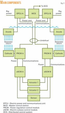
Redundancy at the surface is evident both within the power cabinet, in the form of dual modular supplies running in parallel, and by providing two surface units in a Channel A and B configuration. This parallel independent channel configuration carries through to the actuator itself, ensuring operability of the system despite any single-point failure. Additionally, either channel can be taken offline for any reason while the other continues to function normally.
Two subsea modules serve to regulate power and control tree and manifold functions. Remotely operated vehicles (ROVs) can retrieve both subsea modules.
The first module reduces and regulates the 3-kv input to 300 v DC and separates the communication signal from the power conductor. The reduced voltage and independent communication signal then go to the electric subsea control module. This unit controls valve functions, logs actuator parametric data, receives sensor information, and communicates with surface control equipment.
A fully populated control module currently can operate 16 functions.
Fig. 2 shows the main components along with the master control station, redundant paths, and seawater return.
Qualification
The system is not only a new product line but also an entirely new technology in subsea completions. Because of this, Cameron employed a comprehensive qualification program.
Three levels of testing covered all equipment from the smallest electronic circuit board to large main assemblies. Actual tests carried out and range of test parameters followed international standards where applicable or past experience and good engineering practice where no standard applied.
In some instances, the qualification tests surpassed the guidelines within the standards such as the case with electronic printed circuit boards. The standard stipulates testing of either each individual board or testing of circuit board assemblies. Cameron did both. Because all-electric control is new technology, many of the components are not covered by any standard so that the testing was at a very high level to set a benchmark.
The first level of testing was on the electronic printed circuit board, in accordance with ISO-13628-6 at Q1 level. The guidelines of this testing are:
- Shock30 g acceleration, 11 ms half sine in six directions along three perpendicular axes
- Vibration25 hz ±2 mm displacement, 1 octave/min max, double sweep, 25-1,000 hz 5 g acceleration, 1 octave/min, double sweep, vibration tests repeated for all three perpendicular axes, 2-hr random vibration within following parameters: 20-80 hz at 3 db/octave rise, 80-350 hz at 0.04 g²/hz, and 350-2,000 hz at 3 db/octave roll-off.
- Thermal48-hr soak at 18° C., and 48-hr soak at 70° C.
The second level of testing was at the subassembly level. This included multiple printed circuit boards mounted in a rack or stacked and other smaller assemblies used to build the major assemblies. The level of testing for these units also was according to ISO-13628-6 but at Q2 level. The testing was similar to the above but at slightly less stressful levels as follows:
- Shock10 g acceleration, 11 ms half sine in six directions along three perpendicular axes
- Vibration25 hz ±2 mm displacement, 1 octave/min max, double sweep, 25-150 hz 5 g acceleration, 1 octave/min, double sweep, vibration tests repeated for all three perpendicular axes, 2 hr random vibration within following parameters: 20-80 hz at 3 db/octave rise, 80-350 hz at 0.04 g²/hz, and 350-2,000 hz at 3 db/octave roll-off.
- Thermal48-hr soak at low design temperature of 10° C. closed housing and 18° C. open housing, and 48-hr soak at high design temperature of 40° C. closed housing and 70° C. open housing.
Shock and vibration levels are lower because the mass of the equipment under test is higher and the main purpose of this test is to verify integrity of assembly means and connections.
The third level of testing included each major assembly, such as each size of gate valve, choke, power regulation and communication module (PRCM), and the electric subsea control module (eSCM). Also included in this classification were the electrical connectors and jumper assemblies. Testing for these assemblies took the form:
- Seal test.
- Function test.
- Fail-safe close test (gate valve only).
- Overload test (1.5 × maximum stem force).
- Temperature cycle test (2° C. minimum, 65° C. maximum).
- Hyperbaric to 3,000 m.
- Gate valve endurance cycle test (1,000 open/close cycles).
- Choke endurance cycle test (200 open/close cycles in 5 mm steps to simulate 1,000,000 steps of electrohydraulic choke actuator).
- Shock and vibration (shock: 5g 9 ms half sine four times in six directions, vibration: 10-100 hz 0.6 g rms in three axes, 1.8 g maximum, 4 × 15 min).
Connectors and jumpers were fully tested by the manufacturer to the same international standard.
After fully qualifying all equipment, Cameron ran in stages a series of integration tests to ensure interoperability and verify software operation.
The first stage, called Phase 1A, involved a surface power supply and surface modem driving through a cable length simulator to a variable electronic load and subsea modem in a nonredundant configuration.
Upon completion of 1A, Phase 1B replaced the simulated load with actual subsea equipment including the PRCM, eSCM, and electric actuators still in a single channel.
The final level of testing, Phase 2, duplicated all the power and control elements forming a fully dual-redundant system in a channel A and channel B configuration. Although not officially part of the qualification program, this additional testing was crucial for proving the fully qualified components functioned properly when integrated together.
To document this comprehensive series of tests fully, Cameron created a qualification program dossier with the following documents:
- Qualification program overview that provides a short, concise summary of equipment tested, levels of testing, results and effectiveness of testing, and mitigating steps taken.
- Qualification philosophy that provides references international standards where applicable and justifies types and levels of testing where no standard applies.
- Qualification test plan that includes system description, testing performed before final product qualification, test status table, comprehensive reference to international standards used, and other relevant information covering the full qualification program.
- Failure mode effects and criticality analysis-technical risk assurance process (FMECA-TRAP) summary that lists the studies performed and the results of these studies in both text and tabular form.
Implementation
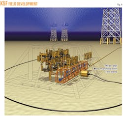
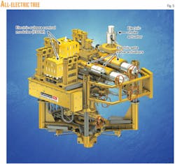
After completion of the field trails in 2004, Cameron started to market the product and in June 2006 received its first order for supplying two trees, including associated all-electric production controls, to be installed inside a three-slot manifold (Figs. 4 and 5). The order was from Total E&P Nederland BV for their K5F field in 121 ft of water off the Netherlands.
In addition to the requirement of controlling the first two tree assemblies, the order also required the subsea production controls be prepared for a future third tree inside the manifold as well as for a future step out of a fourth tree assembly. The distance between the host platform and the manifold is 20 km.
The DC current path uses the coaxial cable inside the control umbilical for supplying power and communications and uses the seawater as its return path. This required four anodes at the platform and four cathodes at the manifold.
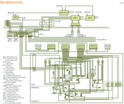
Four electrical power and communication units (EPCU) provide full redundant (Channel A and B) supply for the four power regulation control units (PRCM), which in return send the power and communication signals after regulating it down from 3 kv DC to 300 v DC, to the four electrical subsea control modules (eSCM), responsible for controlling the valves, choke and tree instrumentation (Fig. 3).
A natural consequence on the implementation of the all-electric production controls is that Cameron also had to design, build, and test an all-electric installation and workover control system (IWOCS). This system’s general specifications make it fit for use on other applications as well.
The all-electric DC IWOCS is available on a rental basis and allows either:
- Direct control of the individual actuators by means of connecting at the backend of the actuators.
- Control a complete tree through the eSCM by connecting up to the diver interface panel at the front of the tree.
For this control, the process includes a simplified topside power and communication system consisting of a single channel communication and power supply, as well as an uninterruptible power supply (UPS) to allow stable power supply and a 5-hr standby time with the tree fully open. The design features an IWOCS reel assembly that ends at an IWOCS umbilical termination unit (I-UTA), which in effect is a simplified eSCM.
Aside from the tree being all electric, the downhole safety valve (DHSV) is still an element within the first project that operates in a traditional hydraulic manner. A tree-mounted solenoid valve assembly directly controlled by eSCM operates the DHSV.
Cameron, however, is in communication with various DHSV suppliers and current indications are that the first fully qualified all-electric DHSV will be available in fourth-quarter 2008 or first-quarter 2009.
The two major execution challenges on the first project were:
- Move the product from a research and development into an industrial production environment.
- Manage the first project, while product qualification is ongoing, with improvements and changes implemented on equipment already in production.
These challenges required working closely with a group of selected vendors, already used by the R&D group, through special purchasing agreements for securing production slots and more importantly ensuring that specific knowledge gained by the vendors during the product qualification process would not get lost.
In addition, the project placed special emphasis on identifying critical long-lead items early in and put priority on design freezes for these items. Also the dedicated purchase agreements allowed for the possibility to make changes without having to go through the typical vendor approach whereby there is defined scope agreed and variation orders are used to manage change, which typically take up critical time.
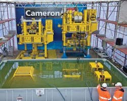
To ensure that the maximum of equipment is tested before going offshore, Cameron has decided for an extensive factory acceptance test (FAT) and a site integration test (SIT) program, which includes two 5-km long coaxial cables simulating the production control umbilical, as well has implemented a water basin filled with seawater, in which to allow simulation of the electrical current return path (Fig. 6).
Installation offshore of the first components started in February 2008.
The authors
Jan van den Akker is manager of DC projects for Cameron’s subsea electric systems, Celle, Germany. He is responsible for execution of the first all-electric tree project and has been working for Cameron since 1990 in various positions. Van den Akker has an MSc in mechanical engineering from Delft University of Technology.
John Burdick is technical manager for Cameron’s subsea electric systems, Houston. He worked previously as a senior electrical design engineer in the subsea drilling controls department at Hydril and as a senior payload safety engineer at the NASA Johnson Space Center. Burdick received a BS in electrical engineering from the University of Houston.
