Advanced gravel-pack modelling improves AICD screen completions
Carlos Pedroso
Enauta Energia SA
Rio de Janeiro
Kesavan Govinathan
Dunefront
Cyberjaya, Malaysia
Ian Mickelburgh
Dunefront
Faro, Portugal
Philip Wassouf
Dunefront
London
Carolina Latini
Dunefront
Rio de Janeiro
Inflow control devices (ICDs) manage reservoir fluid influx along the wellbore to optimize well performance. They contain chokes or tortuous paths which restrict fluid flow based on density or viscosity. Autonomous inflow control devices (AICDs) differ from ICDs in that they have alternative flow paths that restrict flow of selected unwanted fluids (such as water) through the device. The inclusion of ICDs or AICDs in a horizontal open-hole gravel pack (HZ-OHGP) completion, however, results in a difficult completion configuration. These devices put additional pressure against the formation during gravel packing, especially during beta-wave placement, possibly fracturing the well and causing premature screenout.
Risks can be managed with accurate gravel-pack simulations, but modeling flow profiles through ICDs or AICDs at every screen joint requires complex flow-balancing through multiple devices along the length of the completion. Additionally, internal (screen and wash-pipe annulus) and external (screen and open hole or casing annulus) flow paths must be modeled at multiple points in the system. Modelling increases in complexity with number of ICDs or AICDs in the completion.
A complex model is necessary to confirm the viability of an effective pack placement around a screen with an irregular AICD insert distribution and ensure complete screen coverage. A modelling study addressed these issues by comparing an enhanced AICD gravel-packing model with data from an offshore deepwater horizontal gravel pack with AICDs in the completion. The model accurately simulated important features of the job and calculated an overall gravel pack-efficiency of 97% using measured data.
The AICD gravel-packed well has higher daily production, higher cumulative production, and lower basic sediment and water (bs&w) compared with previous wells in the same field, confirming that gravel packs with AICDs are a viable completion technique.
Ultradeep Atlanta field
Atlanta field is an ultradeep water (1,550 m) post-salt oil field in Santos basin, about 185 km southeast of Rio de Janeiro. It was discovered in 2001. Enauta Energia SA (Enauta) is operator (100%). Estimated reserves are 103 MM bbl with 1.29 billion bbl in situ oil volume. The field’s Eocene reservoir has 82-94% net-to-gross, 5 D permeability, 36% porosity, and produces 14° API oil with low sulfur content. High-powered deep-set electric submersible pumps (ESPs) are required to assure commercial production.
The first reservoir appraisal well had a vertical cased hole gravel-pack completion with 91 m of perforations. The well had poor productivity and high skin, suggesting that an HZ-OHGP would be required for field development. The sandstone is characterized as poorly sorted with non-uniform grain size. Low burial depth (800 m) results in a low frac gradient (0.5 psi/ft). These two characteristics challenge HZ-OHGP completions.
The first attempt to complete a well for the early production system (EPS) with an HZ-OHGP was not successful. The well was completed with 10 ¾-in. casing, 9 ½-in. openhole, and 5 ½-in. screens containing 4 ½-in. washpipe. Returns were taken via the choke and surface return line, causing significant back pressure to the formation and impacting overall gravel pack placement. The well was left as a stand-alone-screen (SAS) completion. A well test revealed poor productivity and sand-control issues.
Two long (about 800 m) horizontal wells were subsequently successfully completed with HZ-OHGP under new operatorship in 2012. These wells had larger 6 5/8-in. screens to accommodate larger 5-in. washpipe to increase flow area and reduce friction in the return flow path up the washpipe. Risk of gravel pack-failure was further minimized by using light-weight gravel, reducing carrier brine weight, and adding friction reducer in the carrier fluid to reduce bottom-hole pressure and enable packing below fracture pressure. These changes reduced risk of fracturing-induced leakoff and premature bridging. A retractable casing shoe eliminated a large-diameter rathole, which can cause premature bridging in this section at the start of the alpha wave. Gravel-pack placement was planned using multiple alpha waves and reducing gravel concentrations from the first HZ-OHGP attempt.
The operator is planning eight more wells for full field development based on the successful completion of the first two HZ-OHGP wells and successful AICD gravel packing on the third EPS well.
AICD completion
The Ecocene reservoir has a large active aquifer below the oil rim, and inflow control with isolation was expected to reduce water coning. This technology was avoided for the first two development wells over concerns about gravel packing in a narrow pore-fracture pressure gradient window. Better understanding of the minimum horizontal stress (from leakoff test) and improved modeling of HZ-OHGP in low pressure environments using data from the first two wells provided an opportunity to apply AICD technology for the third well. At a minimum, the screen was expected to be covered by the alpha wave.
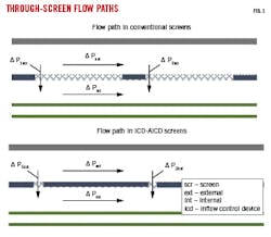
Fig. 1 illustrates flow paths of conventional screens and screens with ICDs or AICDs. Fluid easily flows through conventional screens, redistributing flow at each screen joint to balance pressure drop in internal and external flow paths. Each joint has an independent solution. With ICD-AICD screens, the solid basepipe forces flow through the restricted device orifices, forcing flow to redistribute across multiple joints. The system is coupled, with flow profiles from one joint affecting other joints in the string, and the modelling solution has to balance flow over potentially hundreds of points. Additionally, no generalized model can be made with generic ICD-AICD flow profiles; the model must incorporate specific ICD and AICD device-performance curves.
Enauta chose Halliburton’s Equiflow AICD for flow control (Fig. 2). Before water or gas breakthrough, these AICDs function as standard ICDs using viscosity-based discrimination to impart pressure-drop across the system and even out inflow. After breakthrough, they preferentially restrict unwanted fluids from oil by creating two possible paths: tangential and direct. Low-viscosity fluids take the tangential path which induces rotational motion, imparting higher pressure-drop through the device (Fig. 1, right). High-viscosity fluids take multiple radial passages toward a direct exit and experience lower pressure drop (Fig. 1, left).
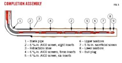
The Atlanta AICD completion design considered expected well production, permeability variation, and pressure drawdown across the sand face. Fig. 3 shows screens with three, six, and eight AICD inserts distributed in sections along the lateral based on these parameters. The sacrificial screen at the toe of the well (7) has no AICDs and returns through it during the alpha wave have low pressure-drop across the screen, reducing pressure on the wellbore and fracture risk. Seal bores (6, 8) above and below the sacrificial screen isolate the screen during production, forcing all flow through AICDs. Gravel-packing pump schedules were revised to account for AICDs once the optimized AICD inserts distribution was decided.
The completion design focused on complete screen coverage and maximum annular packing by performing the following operations:
- Enhanced processing of the sonic caliper log to improve its accuracy.
- Running sacrificial screen below the production screen assembly to allow the alpha wave to be pumped with conventional gravel and at conventional rates.
- Gradually reducing pump rate to prevent significant expected bottomhole pressure increase during the beta wave.
- Reducing washpipe size inside the 6 5/8-in. screens to 4 in. to attenuate beta-wave pressure increase, based on pre-job modelling simulations.
- Discontinuing friction reducer in the carrier fluid due to its inefficiency at the low rates expected at end of the job when pressure-drop would be higher.
- Using a widely adopted gravel-pack placement simulator to carefully model alpha and beta wave development over the irregular AICD inserts to ensure complete screen coverage and packing through open-hole washouts within pump-rate limits.
Additionally, to ensure screen protection and support productivity, gravel pumping was initiated using ceramic gravel with a job design to form a high enough alpha wave to completely cover the entire production screen before covering the sacrificial screen. Since a significant increase in pressure was expected after covering the sacrificial screen, the volume of ceramic gravel was calculated to form about 90% of the alpha wave. The ceramic gravel was then replaced with a more easily transported light-weight gravel, enabling reduction of the pump rate to the operational minimum and reducing pressure drops across the screens during the beta wave. The locally sourced light-weight gravel was a phenolic-coated ground organic material with a nominal density of 1.34 specific gravity (SG).
Three joints of screen with eight AICD inserts each were run inside casing to facilitate beta-wave pack placement towards the heel and ensure packing entered the casing. Pre-job simulations suggested that these 24 ports would enable packing to enter the casing at the minimum pump rate.
While there are several case histories with gravel packs around ICD-AICD screen assemblies, detailed post-job analysis is lacking to confirm how packing proceeded. Limited attempts were made to collect down-hole data on these jobs, and pressure gauges have rarely been included in running assemblies.
On these critical high-profile wells, detailed measurement and recording of all the job parameters would normally be recommended. This would include multiple pressure gauges both above the service tool and along the wash-pipe to enable a more detailed analysis of what happens during packing around ICDs-AICDs.
A simulator that could effectively model packing around AICDs with multiple gravels with different characteristics was not available to the industry when initial Atlanta-field wells were completed, and the third well was the first to be modelled and analyzed. Downhole wash-pipe pressure gauges were run on the first AICD-equipped well (third well in the series), and bottom-hole data was retrieved after gravel pack treatment. Two gauges were run: one at the toe and the other at the heel. The analysis presented in this article is based on readings from the surface and these two down-hole gauges.
Gravel-pack treatment
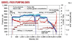
Step-rate tests were used to calibrate pressure drop through flow paths and calculate bottom-hole pressure before gravel pack. Based on the results, the treatment was designed to start at 6 bbl/min with increasing gravel concentration to 0.5 lb/gal proppant added (ppa) using 2.71 SG 16/20 ceramic gravel. Rate increased to 6.5 bbl/min and both rate and gravel concentration were maintained until switching gravel types.
Before the end of the alpha wave, gravel at surface was switched to 1.34 SG 16/20 light-weight gravel, and concentration was reduced to 0.25 ppa to maintain constant gravel volume. Rate subsequently reduced to 6.0 bbl/min to ensure screen coverage along the well before covering the sacrificial screen. After beta-wave initiation, rate was progressively reduced to 1.0 bbl/min. Fig. 4 shows the gravel -pack pump data for the well. The sudden rate drop at about 2,300 bbl was a flowmeter issue, not an actual drop in rate. The well was completed with 755 cu ft of gravel in the open hole.
Job analysis comparing measured data with simulated data was obtained with a conventional gravel-pack analysis workflow. Surface and downhole gauge data (Fig. 5) were imported into the model and time synchronized. Analysis of each stage was done separately as conditions changed from one stage to the next. Friction pressure curves were generated after hydrostatic correction, but actual data from the first job was required to calibrate the model due to convoluted treating lines and complex service-tool flow paths. Only two washpipe gauges were run. One was placed above the casing shoe at the top of the string (WP1-E-P) and the second (WP2-E-P) placed close to the bottom of the screen. Both read externally to the washpipe, monitoring screen-washpipe annulus pressure.
Model calibration required hydrostatic pressure readings at the gauges before starting the job and circulating step-rate test. Data analysis revealed that actual brine weight was 9.28 SG instead of 9.20 SG. Section 1 friction was higher in the simulation than measured, most likely due to changes in actual surface line dimensions over that in the simplified model. Surface line ID was therefore increased to 2 in. from 1.8 in. Section 3 friction was likewise higher in the model than measured. Although the actual specific cause for the lower pressure drop could not be determined, the model was adjusted by increasing service-tool return port dimensions until a match was made. After these calibrations, measured data matched the simulation in all three sections of the well, and the model was ready to evaluate gravel-pack treatment. Critical gravel-pack placement covers blank pipe and screens below the packer in the open hole section. Section 2 pressure measurements include this area. Fig. 6 shows pressures and rates in Section 2 during gravel-pack placement, both with actual (solid line) and simulated (dotted line) responses.
From measured data, gravel was below the packer after 280 bbl, and Section 2 data show alpha-wave deposition in the open hole at 500 bbls where a gradual pressure increase is observed. From 500 to 2,681 bbl, the alpha wave progressed along the open hole with 2.71 SG 16/20 ceramic gravel, as evidenced by the gradual pressure buildup. After pumping 2,500 bbl, gravel was switched to 1.34 SG 16/20 lightweight proppant. Rate was reduced, and pumping continued to 3,200 bbl. Beta-wave packing began at 3,200 bbl as evidenced by the significant pressure increase when the sacrificial screen was covered and all flow forced through the AICDs. Rate gradually reduced until end of treatment.
The simulation followed the overall measured data trend from about 1,600 bbl onward. The model indicates that rate reduction after pumping lightweight proppant at about 3,300 bbl resulted in multiple alpha waves from 3,300 to 3,500 bbl. Multi alpha waves can form when rate is reduced, changing the system balance with more proppant settling on the top of the previously formed alpha wave.
After 3,500 bbl the beta wave reinitiated. Pressure dropped, however, due to a cut in rate rather than the pressure increase usually associated with beta waves at constant rate. Pack efficiency, the actual mass packed in the open-hole section relative to the theoretical mass required to pack the open hole, is 97% in the open hole and casing with only minor topside voids. Fig. 7 illustrates the start of the beta wave (top image) near the toe of the well at 3,600 m, and the alpha-wave height near the heel of 80%. Further alpha deposition occurred as rate dropped, and the height of alpha wave in the bottom image is around 90% ahead of the beta wave. Analysis shows that the screens were completely covered after the alpha wave, with nearly complete packing happening during the beta wave.
Simulated vs. measured washpipe pressure-gauge data closely matched during the job, indicating that the model accurately predicts downhole packing trends with AICDs. Section 3 pressure data also match between model and simulation, however Section 1 data deviate from the simulation when the rate is dropped after beta wave formation. Constant pressure is observed in measured data, but simulated data show a decrease (Fig. 8).
There are three possibilities for this mismatch:
- AICD-port friction may be underpredicted. AICD performance testing was through a maximum of four inserts in a single joint, but multiple inserts across many joints were used in the completion string. Flow distribution through each AICD joint may not be accurately modelled.
- Viscosity in the model may not match actual fluid viscosity. AICD performance is highly sensitive to viscosity. A 1-cp brine viscosity was assumed for the job, but viscosity of the actual field brine, with additives, was not measured.
- Gravel settling in the workstring, restricting uphole flow area during the beta-wave circulation stage, may not have been captured in the downhole model. This scenario is the least likely as light-weight proppant was used during the beta wave. Some of the proppant was observed to be buoyant in the brine and only ceramic gravel was reversed out during the job.
Light-weight gravel to pack the Atlanta well was key to enabling beta-wave placement and achieving effective overall packing of the open hole. The apparent wide range of particle density of the specific product, however, adds a degree of uncertainty to the analysis. Tighter proppant SG specifications for future wells would remove this uncertainty. Improving field-level gravel-pack fluid viscosity measurements will improve modeling results.
Well production
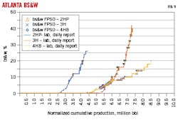
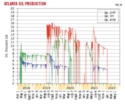
Currently ATL-4H has higher daily production, higher cumulative production, and lower bs&w compared with previous wells in the same field (Figs. 9-10). This confirms that gravel packs with AICDs are not only viable as a completion technique, but also provide the best performance in Ecocene reservoirs.
Bibliography
Pedroso C., Govinathan, K., Mickelburgh, I., Wassouf, P., and Latini, C., “Understanding AICD Gravel Packing,” SPE-206153-MS, SPE Annual Technology Conference and Exhibition, Dubai, UAE, Sept. 21-23, 2021.
The authors
Carlos Alberto Pedroso ([email protected]) is a master completion engineer at Enauta and manages well construction for Atlanta field. He holds an ME (1996) in petroleum engineering from Universidade Estadual de Capinas. He is the current president of SPE Brazil.
Kesavan Govinathan ([email protected]) is a technical sales engineer for Dunefront in Asia. He holds a BS (2012) in chemical engineering from Universiti Teknologi Malaysia.
Ian Mickelburgh ([email protected]) is a business development manager for Dunefront in Europe. He holds a BA (1973) in social sciences from Middlesex University in London. Ian is a 25-year member of SPE.
Philip Wassouf ([email protected]) is managing director of DuneFront in the UK. He received an ME (2016) from Imperial College London and is an active member of SPE.
Carolina Latini ([email protected]) is a technical sales engineer for Dunefront in Brazil. She holds a BS (2015) in chemical engineering from Universidade Federal do Rio de Janeiro.
