New technique combats lost circulation
Matador Operating Corp. combated lost-circulation problems in Monument field, Hobbs, NM, by combining tubing release procedures with a specialized cement-plug setting technique.
Key to the new technique is the use of a sacrificial fiberglass tailpipe, tailored to the length of the lost-circulation zone. Until it is drilled out with the cement, the tailpipe remains in the cement plug that is pumped to stop the lost circulation.
Matador has used the technique in five wells in which circulation was lost completely in depleted zones. In these wells, the technique plugged the lost-circulation zones on the first attempt.
With conventional plug-setting techniques, Matador required an average two to three attempts to set cement plugs, with some extreme cases requiring eight attempts before successfully shutting off the lost circulation.
The conventional techniques resulted in losing 3-5 days/well of rig time.
Other operators drilling in Monument field and surrounding area have used the new method to set a total of 13 cement plugs to date. They have set all these plugs on the first attempt and drilled to the desired TD in all 13 wells.
Field history
The Monument field, now substantially depleted, was discovered in the 1930s. In some areas of the field, the low formation pressure will not support the drilling-fluid column and fluids will be lost to the formation.
Wells drilled through Monument field Grayburg and San Andres formations usually lose circulation between 3,900 and 4,700 ft in extremely pressure-depleted zones that have produced for as long as 70 years.
Two primary mechanisms that cause lost circulation are:
1. Pressure depletion in a highly porous carbonate formation that have as much as 20% matrix porosity.
2. Fractured-vugular intervals that are penetrated by the drill bit with minimal weight on the bit.
Matador and other operators have overcome lost circulation by running an intermediate casing string to cover salt sections down to 2,800-3,000 ft. This design allowed them to drill the main section of the production hole with fresh water, thereby reducing the drilling fluid weight by 1.5 ppg. But offset-well records indicate that lost circulation is still a challenge even with this lower drilling-fluid weight.
The extra cost caused by the lost circulation can make a project uneconomical for wells drilled to 6,800-7,200 ft. Wells deeper than 10,000 ft usually have an intermediate casing string set through the lost-circulation interval, eliminating lost circulation in the production hole.
Matador's standard practice for combating lost circulation in Monument field wells involved spotting cement plugs across the lost-circulation zone after "dry-drilling" through as much of the lost-circulation interval as possible.
This method has the problem of poor cement-placement efficiency because the drill pipe is set above the entire interval. Also, the method usually required multiple cement plugs because of the inability of controlling where the cement went after it left the drill pipe.
Some wells had both long intervals with low pressure and fractures or vugs.
Drilling economics in Monument field are sensitive to cost overruns, so that Matador tries to minimize circulation problems. Wells can be profitable if lost-circulation problems are solved within 1-2 days, but the wells may become unprofitable if the efforts to stop lost circulation continue for a week.
Lost circulation
Proper control of lost circulation while drilling involves keeping the hole full to help prevent a kick, avoiding differential sticking of drill pipe, sealing off the loss zone, and regaining circulation.
One can often correct leakoff by adding lost-circulation material (LCM) to the drilling mud. LCMs can be fibrous (paper, cottonseed hulls), granular (nut shells), or flakes (cellophane, mica).
Complete losses usually require a high fluid-loss slurry squeeze or a hard plug such as cement, cement-bentonite, cement-gilsonite, or diesel-bentonite-cement.1
Matador's previous approach to setting a cement plug included:
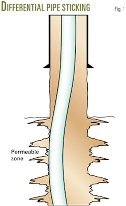
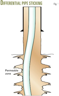
- Going in hole with the drillstring and suspending the string above the loss zone to help prevent differential sticking (Fig. 1).
- Displacing cement above the loss zone and letting the cement fall through the loss zone.
- Continuing to pump displacement fluid onto the top of cement.
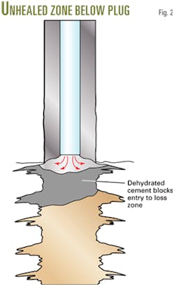
As the slurry falls through the loss zone, the slurry dehydrates and sets, leaving loss zones below unhealed (Fig. 2). Because of this, the pipe may become differentially stuck when the drillstring goes through this loss zone.
In differential sticking, the drill string is held tightly against a permeable formation by a differential pressure.
A filter cake can act as a pressure seal when a stationary drillstring becomes embedded in a thick filter cake on a permeable formation. Differential pressure plus any side forces (pipe weight) can hold the pipe with such force that it cannot be pulled free.2
A survey by a major drilling contractor estimated that stuck pipe (combination of differential and mechanical sticking) caused 36% of the reported drilling problems worldwide over a 15-month period.3 Combined stuck-pipe problems cost the industry more than $250 million annually.4
If a conventional tailpipe is used to place the slurry below the bottom of the loss zone, one risks swabbing part of the plug out as the workstring is removed.
If the wells will not hold a column of fluid, the displacement fluid falling through the drill pipe onto the cement plug may force the plug into the loss zone and destroy cement-plug integrity.
New technique
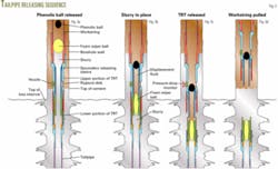
Key hardware in the new technique includes a tubing-release tool (TRT) and a custom-made, fiberglass tailpipe long enough to reach the bottom of the loss interval (Fig. 3a). The bottom of the drillstring is lowered to about the top of the lost-circulation zone. The tailpipe and TRT lower portion are below top of cement and will remain in the slurry across the loss interval.
A rupture disk is an option that enables one to pull the string either wet or dry. Pulling the workstring wet is an advantage because this prevents the drilling fluid from being dumped on the freshly displaced cement.
The rupture disk, however, will burst at increased (4,000-psi differential) pump pressure to allow the fluid to flow out of the workstring.
The nozzle opposite the rupture disk serves as an indicator at the surface. At greater than 2,500-psi differential pressure, the nozzle will open and the operator will observe a lower pressure at surface. This pressure drop indicates that the lower portion of the TRT and tailpipe has parted from the upper portion.
A foam wiper ball, launched from a plug container on the surface, wipes cement slurry from the workstring wall. Behind the foam ball, a launched phenolic ball provides the releasing force that separates the tailpipe for the drillstring.
Fig. 3b shows the deformation of the foam ball as it enters the secondary releasing sleeve while the phenolic ball seats in the releasing sleeve.
At greater than 2,500-psi differential pressure, the TRT parts, leaving its lower section at the top of tailpipe (Fig. 3c). The pressure-drop monitor nozzle then opens to create an immediate pressure decrease that registers on surface instruments.
With the tailpipe and the expendable TRT lower section released, one can pull the workstring without disturbing the slurry (Fig. 3d).
The TRT lower section, in most cases, is constructed of aluminum. One may use, however, a steel lower section if the tailpipe is too heavy to be supported by an aluminum TRT lower section.
The operator also may select a steel lower section if the plug will serve as a kickoff point for a horizontal lateral.
Case histories
In one case, one of Matador's wells experienced 20 bbl/hr drilling fluid losses at 3,716 ft. The rate of the losses continued to increase until the wellbore lost complete circulation with the bit at 4,693 ft. Pump pressure was 400 psi.
Matador set 80, 80, and 50 bbl lost-circulation pills and waited 4 hr after each attempt to allow the pills to heal the loss. It then drilled to 4,850 ft where again circulation was lost. Matador continued to drill dry to 4,933 ft before trying the new technique for setting a cement plug.
In the procedure, Matador set drill pipe at 4,350 ft with a 262-ft fiberglass tailpipe in the lost-circulation zone. Total length of drill pipe and tailpipe was 4,615 ft. The procedure included setting the cement plug, releasing the tail- pipe, and pulling the workstring out of the hole.
After 24 hr waiting on cement, the driller tagged cement at 4,100 ft and began drilling with 12,000 lb on bit at a 55-fph penetration rate.
Rate of penetration (ROP) decreased to 8 fph when the bit contacted the TRT collar. It took 1 hr to drill out the TRT, after which ROP increased to 60 fph. When fiberglass ceased being circulated to the surface, the bit fell through the cement and drilling resumed with full returns.
In another example, a third-party drilling company had complete losses at 920 ft before trying the new technique. In this case, the operator already had pumped two lost-circulation sweeps, with no returns.
The well had 133/8-in. casing set at 830 ft with 232 ft of open hole below the casing. TD was 1,062 ft.
The procedure for stopping the lost circulation included setting the drill pipe at 810 ft, below which was the TRT and 207 ft of fiberglass tailpipe set at a 1,010-ft depth.
After placing the cement plug, the crew pulled the workstring wet and then waited on cement for 18 hr before spending 3.5 hr to drill out the cement, TRT, and tailpipe.
Drilling of the wellbore resumed without any fluid losses.
In a third example, Matador lost circulation in a well while drilling at 3,900 ft. It set a 25 lb/bbl LCM gel pill when fluid loss increased to 25 bbl/hr. Drilling continued as fluid loss increased progressively to 80 bbl/hr at 4,550 ft, then to complete losses at 4,597 ft. After this depth, drilling continued dry to 4,750 ft, at which depth the new technique was applied.
The procedure included setting drill pipe to 4,335 ft with a TRT and a 324-ft fiberglass tailpipe.
After the cement plug was pumped, it took 16.5 hr to wait on cement and drill out the plug before drilling of the wellbore resumed. F
References
1.Petroleum Well Construction, John Wiley and Sons Ltd., West Sussex, England, 1998.
2.Outmans, H.D., "Mechanics of Differential Pressure Sticking of Drill Collars," Vol. 213, Transactions AIME, 1958, pp. 265-74.
3.Jardine, S.I., McCain, D.P., and Barber, S.S., "An Advanced System for the Early Detection of Stuck Pipe," Paper No. SPE 23915, IADC/SPE Drilling Conference, New Orleans, La., Feb. 18-21, 1992.
4.Bradley, W.B., Jarman, D., Plott, R.S., Wood, R.D., Schofield, T.R., Auflick, R.A., and Cocking, D., "A Task Force Approach to Reducing Stuck-Pipe Costs," Paper No. SPE 21999, SPE/IADC Drilling Conference, Amsterdam, Mar. 11-14, 1991.
The authors
Jim Kramer is a senior drilling engineer with Matador Petroleum Corp., Dallas, where he supervises Matador's Permian basin drilling operations and also is involved in various engineering duties. Previously, he has held engineering positions involving drilling, completion, and workovers in various parts of the US. Kramer has a BS in petroleum engineering from Texas Tech University. He is a member of SPE and AADE.
Frank Acosta [frank.acosta @halliburton.com] is an associate technical professional at Halliburton's technology center in Duncan, Okla., where he designs downhole service tools for the cementing casing equipment group. He was instrumental in the development of the tubing release tool. Acosta has a BS in mechanical engineering from Oklahoma State University.
Paul Thornton [[email protected]] is the critical-well coordinator based in Halliburton's field office at Hobbs, NM. In this connection, he designs cementing and stimulation service jobs and provides supervision and technical support. Thornton has been directly involved in the development of the TRT tool and the techniques for pumping cement plugs.


