Shell designed Vito development for present deepwater economics
Shell Offshore Inc.’s new Vito platform incorporated a downsized structure, low equipment redundancy, multitasking personnel, and virtual technology to meet current fiscal restraints for offshore development.
Vito comprises part of the Mars corridor 150 miles southeast of New Orleans in 4,000 ft of water. Mars field was discovered in 2009, and first oil was produced in February 2023. Vito includes a four-column semisubmersible floating production system (FPS) in Gulf of Mexico (GOM) outer continental shelf (OCS) Mississippi Canyon Block 939. The platform has a 100,000-b/d production capacity.
Eight subsea production wells produce from a single drill center 3 miles from the platform. Flowlines and a single umbilical are connected to the FPS with provisions for future tiebacks. Vito produces through an export line to a subsea tie-in to Shell’s Olympus oil line at the nearby West Delta (WD) 143C platform. Produced gas is exported or imported as needed via tie-in to the Olympus gas line. Vito’s design life is 25 years. The project is operated by Shell (63.11%) with partner Equinor Gulf of Mexico LLC (36.89%).
Vito reservoir
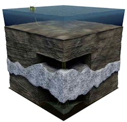
The Vito VM80 reservoir contains late Early Miocene turbidites just south of the greater Mars basin based on five exploratory reservoir penetrations and one southern extended reach penetration outside the reservoir. VM80 is subsalt, sitting in northern traps 6,000 ft below salt accumulations (Fig. 1). Reservoir thickness ranges from 560-1,150 ft with 50-60% net-to-gross (NTG), and the reservoir is split into upper and lower sections.
Exploration and appraisal suggested that the five penetrated reservoir locations were geologically connected through channelized sands (channel facies) in upper VM80 and lobes (lobe facies) in lower VM80. Pressures were commensurate with commingling, suggesting limited reservoir compartmentalization. Current 2P and 2C estimated recoverable resources of the primary Vito development are 290 MMboe.
Fluid viscosity is 2-60 cp with lighter fluids generally at the crest and heavier fluids towards the aquifer. Vito’s net thickness, fluid properties, and small aerial extent—about 1.5 OCS blocks—make it one of the most compact (about twice the density) of typical GOM Miocene fields. The development plan took advantage of this high-density hydrocarbon localization to minimize both the number of wells and the amount of surface equipment.
Drive mechanism
The VM80 reservoir has high initial pressure but low compressibility compared with typical deepwater GOM fields, and it has a weak aquifer. Compaction is an effective drive mechanism for high recovery, but VM80 sands are thick and strongly consolidated. Low reservoir compressibility and limited water drive therefore limit recovery, and gas lift was chosen to compensate for the loss of these drive mechanisms.
Gas lift is expected to improve incremental estimated ultimate recovery by 20-30% and carries less risk and better life-cycle cost efficiency compared with other artificial lift methods available at Vito. Gas lift on Vito requires specialized side pocket mandrels, gas lift valves, and associated intervention tools. Gas lift mandrels were set at about 18,000-ft TVD and contained both barrier valves and shear-orifice valves.
Field exploitation
The original Vito platform concept was similar in size to the Appomattox FPS, but the 2015 oil-price crash affected its size and scope. Project optimization required ranking production scenarios according to key performance drivers including value to investment ratio (VIR), capital intensity, break-even price (BEP), and total net present value. Key threats, opportunities, and most impactful uncertainties were also included for each development scenario.
High value project-decisions included whether Vito should be a subsea tieback or host, the previously-mentioned gas lift options, optimum throughput capacity, and the number of wells and their design.
Subsea tieback was not suitable for VM80’s size, therefore Vito was chosen to be a host platform. From this primary decision, the other project elements were addressed based on maximizing performance drivers and minimizing risk against uncertainties and threats. The competitive scoping process optimized on 7-8 well penetrations with gas lift though two flowlines to a host with 100,000 bo/d capacity.
Ultimate well count balanced risk against production. Seven wells were deemed sufficient to drain the reservoir, but risks included early well failures, poor rock quality, and unanticipated reservoir compartmentalization. An eighth well, therefore, addressed these issues without significantly affecting VIR.
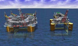
The final Vito platform design scaled to about 2/3 of its original proposed size with cost reduction of more than 70% from the original host concept (Fig. 2). Redundant equipment was eliminated when back-up functions could be handled by other equipment. An optimized production train used an overall system-design strategy to reduce topsides footprint and weight. The reduced and redesigned hull uses an inline mooring tensioner for 12 taut chain-polyester-chain mooring lines securing the platform, removing winch systems from it. The hull was also simplified from traditional FPS with respect to stiffening, ballasting, and equipment.
Operations
The smaller footprint of the Vito platform limited people on board to 60 and required cross-training and combined leadership roles to perform multiple jobs. This cross-training included operations, maintenance, logistics, warehousing, helicopter operations, waste management, and emergency responders. Specific training focused on health, safety, security, and environment (HSSE), government-required certifications, and site-specific commissioning procedures. The last was aided by a process simulator and 3D virtual reality model.
Remote monitoring and control were included on a more intensive level than on traditional deepwater platforms. A remote control room (RCR) in New Orleans supports the offshore control room with the same functionality as the onboard room. It can operate the distributed control system, radar systems, and multiple communication platforms to the host. Operators rotate between the RCR and the offshore control room, keeping active knowledge of platform operations and platform-specific issues fresh between locations.
Vito has a digital twin with a front-end for integration and visualization, a backbone that links everything together through an engineering data warehouse, and a back-end document management system. Workers performing surveillance rounds connect through mobile devices accessing multiple sources, including the digital twin, for procedures and drawings as required on deck. The devices eliminate printed documents which may be out-of-date and uncontrolled.
Shell is piloting virtual reality (VR) and extended reality (ER) systems to reduce offshore trips and operate within Vito’s people-on-board (POB) limits. VR headsets connect offshore crews, onshore teams, and vendors with shared screens for real-time visual inspections. Equipment mark-ups and drawing annotations are collaboratively performed among remote participants. The system will be used for startups, shut-ins, quality assurance-quality control validations, and incident investigations without the delay, expense, or risk of sending specialists offshore.
Maintenance
A reliability-centered maintenance (RCM) program replaces corrective maintenance with condition-based maintenance to minimize unexpected downtimes. RCM, in descending order of priority, includes:
- Predictive maintenance based on proactive surveillance and condition assessment.
- Maintenance based on time or run hour.
- Equipment repair or replacement after failure.
The first method requires online and offline condition-based performance monitoring and non-intrusive monitoring and inspections. Using RCM, true production-critical equipment was identified based on the impact and consequence of failure. Critical spares were ranked against a maintenance efficiency index, with POB limitations included in the assessment.
Spares were divided between capital spares (high cost, long lead times, capitalized and depreciated) and operational spares (lower cost, expensed). Operational spares were given the same importance as capital spares based on their criticality to operations. Spare stocking was based on purchase costs, mean time to-failure, applications specific to Vito, and HSSE impact from failure.
The maintenance strategies are compliant with US Coast Guard regulations and Bureau of Safety and Environmental Enforcement requirements for safety and environmental management systems (SEMS) and process safety management (PSM). Vito is the first RCM-compliant site in Shell’s GOM portfolio and has a validated 20-year life-cycle plan.
Drilling, completions
Wells drilled in batch mode before first oil maximized value and minimized drilling risks from depletion. Casing designs were standardized to reduce cost. All eight wells are subsea with 15,000 psi trees and were successfully drilled between 2018 and 2020. The wells confirmed high NTG and good communication across the field, like the exploration and appraisal wells.
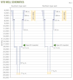
Fig. 3 shows schematics for northern and southern wells. All riserless top holes to the 22-in. casing shoe were batch drilled to about 8,000 ft MD. All 38-in. casings were jetted to planned depth with a low-pressure wellhead housing, leaving about 10 ft of stickup above mud line and less than 50-ft center-to-center well separation. Inclination was less than 1°.
The 26-in. hole was drilled with 12.5-13.5 lb/gal (ppg) pad mud which produced gumbo. All 28-in. and 22-in. casing strings successfully ran to planned depth. Foam cement was used on all 22-in. cement casing jobs and on one 28-in. cement casing job which experienced shallow water flow while drilling. After setting and cementing the 22-in. casing, a pressure test confirmed isolation and a balanced cement plug was set above the shoe track to suspend the wells. A modified temporary abandonment cap with a hydraulic hose covered all exposed seals. Preservation fluid was pumped offline with a remotely operated vehicle which saved about 2 hrs of rig time per well.
For completions, wells were re-entered and deepened to TD. All 12 ¼-in. casing strings were successfully run and cemented. This was critical to placing gas lift valves at required depths.
The 9 7/8-in. x 10 5/8-in. (reamed) hole section was drilled from salt to top of reservoir. The 7 5/8-in. liner successfully landed on all wells above the top of reservoir. Most wells used a 7 5/8-in. casing reamer shoe to get to bottom due to the need to remove hole fill. An additional 9 7/8-in. liner was required in the south due to overburden differences.
Good cement placement across the production packer setting depth about 1,000 ft above the 7 5/8-in. shoe was critical to providing zonal isolation. The upper VM60/65 reservoir is water-filled while the VM80 target reservoir is oil-filled. Although initially over pressured, VM80 pressure is expected to deplete to VM60/65 pressure, resulting in potential water crossflow if the liner is poorly cemented.
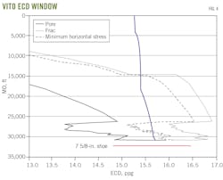
Open holes completions covering the entire VM80 reservoir were chosen for low skin and cost competitiveness compared with cased-hole completions. Vito slim-hole drilling is below fracture gradients (Fig. 4). Water-based CaBr2 DIF with breaker was designed especially for Vito conditions. Equivalent circulation density (ECD) management, shale swelling and osmotic impact studies, operational procedures to minimize pressure cycling on shale, and extensive DIF testing ensured that drilling remained within the safe pressure window. The system was tested in the laboratory, had good stability in the field, and delivered low-skin completions.
The bottom hole assembly (BHA) was chosen to address the following, in order of importance:
- Minimize vibration and BHA failure risk.
- Provide minimum logging requirements.
- Allow for sufficient hole cleaning.
- Maintain tangent section.
- Minimize hole tortuosity.
- Optimize rate of penetration.
- Provide a single BHA run.
The wells were run in with combined lower openhole and upper completion equipment. Openhole gravel packs (OHGP) provided sand control and shale isolation. The gravel pack screened out in the first well. Subsequent wells were reamed to 7 in., and the screen basepipe was reduced from 4 in. to 3.5 in. to provide additional annular space for the gravel pack. All subsequent screens were successfully packed.
The upper completion consisted of tapered 5 ½-in. x 4 ½-in. chrome production tubing with deep gas lift mandrels and permanent downhole pressure gauges near the bottom of the 12 ¼-in. liner.
Gas lift
Gas lift was selected over electric submersible pumps due to lower intervention costs and full bore access. Up to 100 MMscfd of gas at 6,000 psi is available on platform for gas lift. Gas-lift design includes 17,000 psi back-check differential pressure valves, 15-MMscfd flow rate/well, 10,000-psi maximum injection pressure, and 300° F. operating temperature through a single gas-lift mandrel. These conditions are outside the operating envelope of current gas-lift applications and required a fit-for-purpose gas-lift kit.
Computational fluid dynamics evaluated erosion, flow-control device (FCD) chatter, and port size. Physical flow testing was conducted at Southwest Research Institute’s flow loop to determine the range at which the FCD will chatter and ideal port size for correct injection volumes. Finite element analysis was used for structural integrity assessment of all tools for Vito’s gas lift system (FCD, latches, side-pocket mandrel, kickover tool, and running-pulling tools).
Tests of commercially available nonmetallic samples for FCDs initially failed operating condition tests. A revised test program adopted new test guidelines from API RP17D and API TR6JI and provided acceleration-aging test guidelines. At the conclusion of the test program, nonmetallic gas-lift packing materials were identified and approved for Vito conditions.
Production
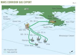
Vito oil is exported via an 18-in. line to the Olympus oil lateral at the existing subsea wye at the base of the WD143C jacket (Fig. 5). Gas export is via a 10-in. line to the existing mid-line wye sled on the Olympus gas lateral in MC718. Additional Vito gas required pump updates at WD143C and debottlenecking at the on site Enbridge Inc. gas plant.
Additional developments in the Mars corridor require three new pump modules at WD143C to reroute Mars A and Ursa oil via existing bridge piping from WD143A to WD143B. New piping was installed to WD143C, and the existing 24-in. line was abandoned.
Start-up, ramp-up
Difficulties for start-up included limited deck space for temporary equipment, limited POB, and no test separator for well routing during unloads. Also, Vito operators were not initially familiar with the simpler host and subsea system design, and RM80 has different produced fluid properties than typical GOM operations. These factors introduced unknown risks during startup and ramp-up.
To study these issues, a dynamic simulator trained personnel and tested start-up procedures before actual platform commissioning. The simulator contained all wells, flowlines, risers, fluid processing, gas-lift system, gas buyback, flare, and other relevant production utilities. The simulator addressed:
- Step-by-step validation of operational procedures.
- Well start-up unloads.
- Operator training on new equipment and operating conditions, including gas lift post first-oil.
- Validation of operational setpoints and interlocks.
- Fluid-property problems such as high viscosity.
The water treatment system was isolated throughout the unloading period. Relevant midstream companies approved a subsea and topside chemical treatment plan sufficient for pipeline export.
Before first oil, subsea flowlines were pressurized with nitrogen after complete flushing and hydrotest to provide nitrogen for topsides pressure testing and commissioning before startup. Gas buyback took place before first oil to supply gas for commissioning compressors without requiring temporary diesel-powered or gas-storage equipment before produced-gas availability.
Optimizing well-unload intervals within the startup sequence allowed for quickly reaching plateau while maintaining adequate time for subsurface data acquisition and surveillance. Various ramp-up sequences were analyzed by an integrated team evaluating optimum startup sequence, well-unloading intervals, and sequence timing.
Bibliography
Rabel, R., Freeman, S., Adams, E., and Pillai, P., “Vito Project:Drilling & Completions – World Class Riserless Batch Set Performance, Best-in Class Deepening Performance, In-Well Barrier Gas-Lift System, 17 Ksi Barrier Checks, 15 MMSCF/Day Injection Rate,” OTC-32414-MS, Offshore Technology Conference, Houston, Tex., May 1-4, 2023.
Rincon, J., Greenlee, I., Hamerski, R., Rayborn, J., and Schexnayder, J., “Vito Operating Model & Start-Up Ramp Up (SURU),” OTC-32496-MS, Offshore Technology Conference, Houston, Tex., May 1-4, 2023.
Shallenberger, K.D. and Fresquez, S.M., “Vito Project Overview,” OTC-32254-MS, Offshore Technology Conference, Houston, Tex., May 1-4, 2023.
Sorgard, E., Oko, E.A., Baird, J.I., Greenaway, J.A., Rabei, R.I., and Pillai, P., “Vito Project: Vito Field Development,” OTC-32319-MS, Offshore Technology Conference, Houston, Tex., May 1-4, 2023.
About the Author
Alex Procyk
Upstream Editor
Alex Procyk is Upstream Editor at Oil & Gas Journal. He has also served as a principal technical professional at Halliburton and as a completion engineer at ConocoPhillips. He holds a BS in chemistry (1987) from Kent State University and a PhD in chemistry (1992) from Carnegie Mellon University. He is a member of the Society of Petroleum Engineers (SPE).
