Bradenhead cementing isolates Permian basin surface casing
Bradenhead cementing, where pressure is applied to the entire casing string, improves cementing operational efficiency and economic viability. It isolates the vertical part of the wellbore from stimulation pressures in the uncemented lateral and controls cementing under disparate pressure gradients between the overburden and the reservoir.
Occidental Petroleum Corp. performed bradenhead cement jobs in New Mexico’s (NM) Permian basin. Well designs included casings penetrating salt strings, casings set with shallow-set shoes, and casings set with deep-set shoes. Cement-bond logs (CBLs) showed that bradenhead jobs generally resulted in good cement-to-surface bonding, but further work is required to improve cement placement and casing bonds.
Bradenhead cementing
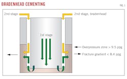
Bradenhead cementing is performed as a second stage of the cementing process after conventional cementing (Fig. 1). The technique injects cement into the formation from the annulus using conventional cement formulations and densities in cases of low formation pressure or overpressured upper sections. It is a combination of reverse cementing, multistage cementing, and remediation. It has become the primary cementing solution across multiple New Mexico Permian basin fields with stacked production intervals beneath shallow mining and groundwater resources.
Conventional cement circulation becomes unreliable with increased MD and TVD. Equivalent circulation densities (ECDs) and overburden pressure increase with openhole exposure. Isolation along the entire interval with cement pumped in a single stage increases in difficulty in underpressured (< 8.34 lbm/gal (ppg)) or overpressured (>9.4 ppg) formations.
The NM Delaware basin contains such abnormally pressured formations from saltwater disposal injection into the Bell and Cherry Canyon formations overlying subnormal depleted formations. These sections must be drilled before reaching a set casing point and setting a shoe. Conventional methods achieve cement-to-surface in this area using water-extended cement, foam cement, low-density high-compressive-strength cement, reverse cementing, and multistage cementing.
In bradenhead cementing, the first stage is pumped conventionally with top of cement (TOC) planned below the top of a depleted weak zone. After the first stage, cement lines are transferred from the cement head at the rig floor to the production annulus wellhead valves. Both lines are required for effective cementing.
The second (bradenhead) stage pumps a small volume of water at increasing flow rates to establish injection (without exceeding the formation integrity test (FIT) value of the previous casing shoe). This test establishes the maximum allowable annular surface pressure (MAASP). Bradenhead cementing ECD must be accounted for when planning an FIT, and the authors recommend a leakoff test instead of an FIT to increase injection pressure limits.
For subnormally pressured formations where weak zones have fracture gradients below 8.34 ppg, a nonaqueous reactive spacer (NARS) is pumped ahead of the bradenhead cement, and a lost circulation material (LCM) is added in the initial bradenhead volume.
Once pumped, the second-stage cement drops until reaching equilibrium between hydrostatic pressure and pore pressure of the weakest zone taking fluid. TOC in bradenhead cementing tends to be inconsistent and needs confirmation for every job with cement bond logs (CBL), ultrasonic imaging tools, fiber optic logs, temperature logs, or other methods.
Permian basin well conditions
Well designs in the NM Permian basin contain shallow intermediate strings set below salts in the Lamar formation at the top of the Delaware Mountain Group (DMG). The vertical production section is drilled through the DMG. Casing and TOC requirements are dictated by regulations protecting potash and freshwater sources. In these instances, cement is required to surface on the first two or three strings of casing.
Bradenhead cementing uses 12.8 ppg slurry regardless of formation depletion, resulting in higher cement uniformity, faster setting, better shear bonds, and higher compressive strength over conventional cementing alternatives. The uniformity improves repeatability and lowers costs across the drilling region. By using higher density first-stage cement for deeper interval isolation and setting casing packoffs, the bradenhead second stage can be deferred offline after the rig is moved to the next well, improving rig drilling-time efficiency. This can result in significant rig-time savings as estimating TOC with the bradenhead technique is unreliable and top-ups are frequently needed after waiting for cement to set.
The generic bradenhead cement design for depleted weak zones in the Brushy Canyon formation calls for pumping the first stage conventionally with TOC planned 250 ft below the top of a depleted weak zone. In cases of shallow previous casing shoes, FIT and MAASP decreases, increasing difficulty in establishing an injection test in weak formation zones.
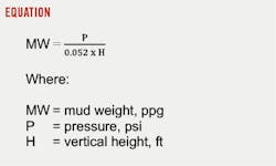
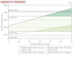
Fig. 2 shows the difference in surface pressures to break down the weak zone during FIT between two casing set depths and two different formation gradients. Required annular pressure to initiate injection increases with open hole length and setting depth, therefore less surface pressure is available to initiate losses in weak zones when pumping a bradenhead cement job for a surface casing annulus than for an intermediate casing annulus. This is described by the equation which shows that the deeper the shoe, the lower the equivalent mud weight under the same surface pressure. For example, a 20-ppg equivalent mud weight FIT at a 500-ft TVD surface shoe is equivalent to 520 psi, but it is equivalent to 4,680 psi with an intermediate shoe set at 4,500-ft TVD.
A shallow shoe set at 450 ft will require at least a 19.5-ppg FIT or higher (light green shaded area in Fig. 2) to avoid breaking down the shoe versus the weak zone with a 9.2-ppg fluid. A deeper shoe set at 750 ft allows a wider range of FIT values depending on the Brushy limits and mud weights.
To mitigate bradenhead breakdown failure in shallow casing designs with TOC at surface, a scavenger-cement blend is pumped in the first stage to act as a weighted spacer with a gel-strength profile to break down the weak formation as it is pumped up the annulus. The scavenger induces losses and acts as insurance in case the second-stage bradenhead cementing job does not pump into the required formation.
NM bradenhead case histories
Bradenhead cement jobs were performed on wells which penetrated the Brushy Canyon formation in NM with planned TOC about 250 ft below the top of these depleted weak zones. CBLs quantitatively determined bradenhead cementing effectiveness in the intermediate casing string (75/8-in., 26.4 lbm/ft, 80 ksi high-collapse performance) using amplitude data. CBL results were averaged across multiple wells.
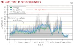
The first application was in an area with a salt string from 4,100-4,300 ft MD and severe depletion. Fig. 3 shows average CBL results from 11 wells. Average amplitude (in mv) is green, average third-quartile amplitude is blue, and average 90th-percentile amplitude is grey. The free pipe zone outlines amplitudes of a poor cement bond. The yellow dashed line is the maximum acceptable amplitude agreed upon with a regulatory office for 75/8-in. casing when evaluating cement-in-place using amplitude alone. The advantage of isolated amplitude analysis is that it compares large CBL datasets without additional interpretation required for other performance metrics such as a cement-bond index.
Average amplitudes for the 11 wells were below the free pipe zone, indicating good cement bonds, though some wells were above the maximum allowable threshold. Wells with amplitudes more than 30 mv below the shoe had higher-than-average injection pressures leading to breakdowns of the salt-string shoe. The NARS, pumped ahead of the bradenhead cement in these severely depleted wells, appears to have caused the higher injection pressures and was eliminated from the program for later wells. Removal of NARS did not affect cement placement, and injection pressures were normal on wells subsequently pumped without NARS.
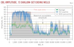
The next series of wells included shallow surface casing shoes set from 400-650 ft MD in competent Brushy Canyon formation with 9.8-10.2 ppg pressures. The formation and shallow shoe required cement adjustments over the previous jobs with a scavenger added as lead cement. Fig. 4 shows average CBL from 13 wells. The results show that some well CBLs were in the free pipe zone, indicating that the bradenhead portion of the cement job was either injected into the surface shoe but did not make it to the Brushy Canyon formation, or did not bond to the casing. Average amplitudes, however, were below the 30 mv threshold.
Subsequent wells were modified to avoid surface shoe breakdown by setting shoes at the deepest extent allowed by regulating agencies. TVD was increased 300 ft where applicable, and scavenger density was increased to assist in breaking down the formation before the bradenhead portion of the job.
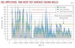
The third set of wells treated with bradenhead cementing had surface casing shoes set at 900-1,050 ft MD, deeper than in previous wells. In these wells, Brushy Canyon fracture pressure was < 9.2 ppg and scavenger acted as lead cement. Fig. 5 shows CBL results from two wells in this area. No shoe breakdown was observed due to the weakened formation, but coverage was still sporadic and frequently more than 30 mv below the shoe to about 4,000 ft MD. At this depth, the well encountered salts and anhydrites. Anhydrites show faster CBL response times than casing, complicating CBL interpretation from 4,000-11,500 ft MD.
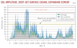
Improvements to the cementing design included the addition of expanding cement in the scavenger. Tests showed that the scavenger would expand about 2% in volume when using a 3% concentration of expanding agent. Fig. 6 shows results from wells with the same design as Fig. 5 but with expanding agent in the scavenger. Cement bond improvements were observed from 1,500-4.500 ft, though still with uneven coverage and occasional free pipe. Additional improvements to bradenhead cementing to address these shortcomings involve potentially rotating pipe, increasing concentration of expansion additive, or adding a foamed stage.
Additionally, gel strength needs to be better understood in the annular fluid column before the bradenhead stage. Yield points may not provide sufficient information on fluid rheology. Precise static gel strength measurements to at least 300 min, beyond the typically reported 60-min gel values, would provide better estimates on surface pressures required to perform the cement job.
Based on “Unconventional Bradenhead Cementing in the Delaware Basin Case History,” SPE Drilling & Completion, Vol. 38, No. 1, March 2023, pp. 110-119.
About the Author
Alex Procyk
Upstream Editor
Alex Procyk is Upstream Editor at Oil & Gas Journal. He has also served as a principal technical professional at Halliburton and as a completion engineer at ConocoPhillips. He holds a BS in chemistry (1987) from Kent State University and a PhD in chemistry (1992) from Carnegie Mellon University. He is a member of the Society of Petroleum Engineers (SPE).
