Abandoned-well wireless gauges prove reservoir connection
ExxonMobil installed a wireless-gauge long-term monitoring system (LTMS) in an abandoned Cyprus Block 10 wildcat well for long term, far-field reservoir monitoring. The LTMS revealed dynamic communication with the appraisal well, improving reservoir description and reservoir modeling. The LTMS installed directly into the abandoned well, requiring little additional equipment and rig time.
Reservoir interference
Interference tests measure responses between producer or injector wells and one or more observation wells to delineate reservoir compartmentalization and provide drilling guidance and reservoir management. These tests outline reservoir extent and connectivity better than single-well shut-in tests, in which shut-in takes too long to define far-field structures, if they can be defined at all, and built-up pressure data requires substantial analysis. Interference tests, by contrast, provide relatively quick results with direct directional and depth responses, requiring little interpretation.
Interference tests during field appraisal usually require LTMS using wired gauges on tubing which needs to be retrieved before well abandonment. Wireless gauges using acoustic telemetry are available, but the signals cannot penetrate cement plugs in abandoned wells and, therefore, the wells must remain live during the interference test phase.
Wireless electromagnetic telemetry
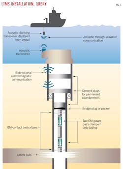
By contrast, wireless gauges using electromagnetic (EM) telemetry enable tubingless installations in abandoned wells from which data can be accessed at the seafloor (Fig. 1). Bottomhole lithium battery-powered quartz gauges record hourly pressure and temperature data in memory. System life ranges from 6 months to 7 years depending on transmission frequency and reservoir temperature.
Resolution is 0.01 psi and 0.2° F. Contact centralizers connect the assembly to the casing and send EM signals to a transceiver mounted on a wellhead debris cap. The transceiver decodes EM signals into pressure and temperature data and converts them into acoustic pulse data. A quartz gauge on the wellhead measures hourly seabed pressure for local tide analysis.
At surface, a dunking transceiver lowered 30-60 ft into the water above the wellhead communicates acoustically with the subsea transceiver. Communication is bidirectional to change bottomhole gauge transmission schedules and extend battery life or query other data. Communication between gauges and seabed are through a single hop or with multiple repeaters if signal strength requires boosting in deep and ultradeep water.
EM LTMS has been used for interference testing between abandoned deepwater appraisal wells and nearby producers during field production. The current work is possibly the first application of an abandoned wildcat well used for monitoring during field appraisal. Problems experienced performing tests at the appraisal stage included:
- Fewer reservoir penetrations increasing uncertainty in subsurface knowledge for guidance of interference tests.
- The battery life of an EM LTMS system sometimes being shorter than the appraisal period.
- Without production facilities, interference tests depend on drilling rig availability, requiring that temporary test well completions be installed and retrieved, again extending the appraisal phase possibly beyond battery life.
- Drawdown-pressure buildup tests are preferred over injection-falloff tests for thermodynamic and multiphase flow reasons. But without production facilities, produced hydrocarbons require collection and disposal, biasing tests towards injection-falloff.
For appraisal-level interference tests, signal amplitude is controlled by in-place volume, formation compressibility, and aquifer details. By contrast, far-field connectivity controls lag time. The signal needs to account for gauge resolution, drift, and noise. For offshore tests, the data need to be checked against tidal effects. Installing gauges well before interference testing establishes baseline responses to long-term drift and tidal effects. The latter is important because data collection is typically out of sync with the 12.42-hr tidal period, resulting in inconsistent ability to measure the influence of tides upon gauge response.
Cyprus interference test campaign
Initial Cyprus Block 10 exploration consisted of two wildcat wells but did not include well tests. Discovery well Glaucus-1 (G-1) found high-quality gas-bearing formations which were targeted for further appraisal. The well was subsequently cased.
Cutting casing across pay established communication between the wellbore and formation. Injection tests confirmed connection. Two sets of dual gauges were run on a bridge plug before pumping multiple shallow cement plugs for permanent abandonment. LTMS successfully queried all four gauges wirelessly from the rig. Pressure readings indicated a 9.4 pound per gallon (ppg) (0.49 psi/ft) gradient over 138 ft between the gauge sets, corresponding to the non-aqueous fluid (NAF) gradient left in the wellbore when the well was suspended. Reservoir gas at 0.10 psi/ft is expected to swap with the NAF, and the progress can be monitored with the gauges.
Delays in the Glaucus appraisal campaign scheduled interference tests at Glaucus-2 (G-2) 3 years after G-1 LTMS installation, twice the expected timeline. The downhole system had the battery capacity to withstand this delay due to low reservoir temperature and a 14-day transmission schedule. The subsea transceiver, however, was retrieved to replace its batteries. During this operation, 2.5 years of pressure data were downloaded for baseline analysis and to change the resolution of transmitted data from 0.1 psi to 0.01 psi.
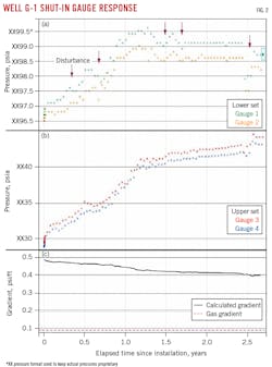
Although there was pressure communication to the reservoir through the casing cut, fluid loss agents in the NAF limited fluid leakoff and gas swap-out to the reservoir. The arrows in the lower-set gauges (Fig. 2a) show fluctuating pressure readings exceeding tidal effects, indicating that gas was not continuously migrating through NAF but built up at the casing cut until forming bubbles large enough to migrate through the gelled NAF. The lower-set gauges (Fig. 2b) were covered by NAF in the first year but exhibited a 2-psi increase as the NAF lightened from a density gradient in the emulsion formed by partial phase separation and barite sag and reservoir gas dissolved into the NAF.
Upper gauge readings continued to fluctuate due to continual NAF swap-out into the interference test stage and they could not be used to discriminate reservoir response from fluid swap-out drift. The lower gauges, by contrast, exhibited steady responses 1.7 years after installation, indicating that the NAF reached steady-state condition and level at the lower gauge depths. The lower set of gauges, therefore, provided accurate reservoir signal responses.
Interference test
Well G-2 was about 1.5 mi from G-1. The G-2 interference test was conducted 3 years after G-1 LTMS installation, well within the battery limitation of the wireless gauge clusters. Subsurface, operational, and NAF swapping-sagging concerns dictated a minimum depletion of 0.5 psi in the test design.
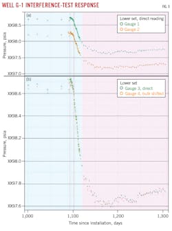
Fig. 3 shows the G-1 LTMS lower-set gauge readings over a 320-day period in the first data query, straddling the G-2 well test (red dashed lines show start and end of G-2 flow). The gauges transmitted separately to avoid clashes and to sample different tidal cycles. Fig 2a depicts readings as recorded and Fig 2b shows Gauge 2 readings bulk-shifted by depth to those of Gauge 1, which helps confirm accuracy of the readings.
About 25 days after the G-2 well test, both gauges recorded pressure drop of more than 0.7 psi, indicating interference between wells. Additional data were required to verify that this was a real reservoir response. About 6 months later, the LTMS was queried a second time (data in pink shaded area of Fig. 3) and showed continual pressure decline, totaling 1.1 psi, before pressure increased due to reservoir recharge. These data confirm connectivity between the wells. Tidal effects are observed in 0.06 psi fluctuations in the recovery data.
Based on “Abandoned Exploration and Appraisal Wells Turned into Long-Term Monitoring Wells for Enhanced Far-Field Reservoir Characterization: Lessons Learned from a Frontier Deepwater Installation,” SPE-212628-MS, presented at the SPE Reservoir Characterisation and Simulation Conference and Exhibition, Abu Dhabi, UAE, January 2023.
About the Author
Alex Procyk
Upstream Editor
Alex Procyk is Upstream Editor at Oil & Gas Journal. He has also served as a principal technical professional at Halliburton and as a completion engineer at ConocoPhillips. He holds a BS in chemistry (1987) from Kent State University and a PhD in chemistry (1992) from Carnegie Mellon University. He is a member of the Society of Petroleum Engineers (SPE).


