Subsea coiled tubing reentry P&As wells from MSV
Based on “Successful Subsea Reentry Well Abandonments with Coiled Tubing Deployed from a Multiservice Vessel in the Gulf of Mexico,” presented at the 2022 SPE Subsea Well Intervention Symposium, Galveston, Tex., Aug 9-11, 2022.
Schlumberger, Helix Energy Solutions, Drilling Services of America, and TAM International performed two subsea reentry abandonment operations in the Gulf of Mexico from a multiservice vessel which required novel wellbore access solutions in combination with coiled tubing reentry. The interventions required milling cement plugs, perforating and isolating annular spaces, running inflatable cement retainers, and pumping cement. This was the first integrated application of these techniques from a multiservice vessel.
More than 1,400 wells are waiting to be plugged and abandoned (P&A) in the Gulf of Mexico, requiring either dynamically positioned semisubmersible drilling rigs or multiservice vessels (MSV) for deepwater subsea well interventions. Rigless coiled tubing (CT) interventions from a multiservice vessel are the most efficient and cost-effective.
Well abandonment
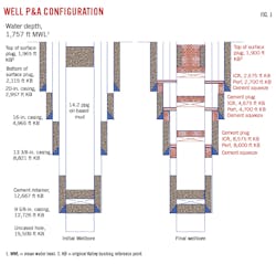
The operator required permanent P&A of two nonproducing exploration subsea wells temporarily abandoned in 1997-98. Temporary abandonment was performed by setting surface cement plugs just below the mudline (within 500 ft) in 9 5/8-in. casing (8.535-in. ID) at 1,760 ft water depth. The wells were suspended with 14.2 pound per gallon (ppg) oil-based mud below the cement plug and had similar completion configurations. Scope of the permanent P&A work included removing surface cement plugs and leaving the wells in full plug and abandonment states per the Bureau of Safety and Environmental Enforcement (BSEE) Title 30 CFR §250.1715 (BSEE 2020). Fig. 1 shows well conditions before and after the permanent P&A operations.
Intervention began by drilling out full-bore cement plugs from 1,942-1,965 ft measured depth (MD) at 0° wellbore inclination. Subsequent annular isolation used a combination of decentered casing perforations, high-expansion inflatable cement retainers (ICR), and cementing. All annuli communicated with open hole extending to mud line, therefore isolation required cement plugs at least 200 ft long in the annular space. Workscope included four main stages:
- Milling out surface plugs set inside 9 5/8-in. casing.
- Isolating the 9 5/8-in. x 13 3/8-in. annulus.
- Isolating the 16-in. x 13 3/8-in. annulus.
- Isolating the 20-in. x 16-in. annulus.
Pressure below cement plugs was unknown, therefore wells were assumed live for safety considerations. The CT unit used a high-pressure 7 5/8-in. intervention riser system (IRS) with 6.31-in. internal drift diameter run from the MSV to mudline.
CT design
Typical CT sizes deployed in GOM are from 1 ¼ in. to 2 in. and up to 30,000 ft long, but these were not sufficient to mill inside 9 5/8-in. casing due to friction pressure limitations. A custom 2 3/8-in. CT string was ordered to meet the following criteria:
- CT must enable pump rates greater than 3 bpm for efficient hole cleaning while minimizing friction pressures to reduce bend-cycle fatigue and ballooning.
- CT must provide sufficient weight on bit (WOB) for optimal rate-of-penetration and sufficient overpull at the deepest point in the well to reduce stuck pipe risk.
- CT must provide optimal bend-cycle fatigue survivability and ballooning to maximize service life of the string.
- CT must be compatible with standard available surface equipment without requiring custom conversion.
- CT must shear with the vessel’s IRS shear ram under worse-case wellhead pressure to meet BSEE qualifications for this work.
CT wall thickness (WT) choice considered several factors. Thick-walled strings provide better bend-cycle fatigue life and less ballooning, but thicker walled CT increases circulation pressures and shear difficulty. Milling operations inside large ID holes require high circulation rates for good hole cleaning.
Shear calculations suggested a maximum WT of 0.204 in. and limited material grade to 100,000 psi minimum yield strength (G100). This WT withstands expected reactive forces during milling. Single-wall construction (without tapered design) was acceptable for the string due to the wells’ relatively shallow (2,000 ft-4,000 ft) working range.
The CT string provides sufficient strength for all operations and enables fluid circulation at required pump rates while maintaining fatigue and ballooning within safety margins. After subsea BOP shear tests verified shear calculations, two 2 3/8-in., 0.204-in. WT, G100 spec, 12,000-ft CT strings were obtained (one operating, one backup).
Hole cleaning
CT restricts flow rates for hole cleaning on milling operations from high pressure drop through the small-coil ID choke bottom hole assembly (BHA). The downhole motor also has a maximum operating flow rate limitation. To minimize ballooning and bend cycle fatigue, maximum pump rate was limited to 3.5-4.0 bpm, providing 54-62 ft/min annular velocity in the 9 5/8-in. casing and 100-115 ft/min in the riser. This low annular casing velocity is not sufficient to transport larger cuttings out the annulus with seawater or brine, and an alternative diutan biopolymer fluid was chosen for cuttings transport in milling operations.
The biopolymer was shear-thinning for increased carrying capacity at low annular velocities and lower friction pressures inside the CT. Hole cleaning and hydraulics modelling showed that the fluid could lift 0.45-in. diameter cuttings at 4.0 bpm maximum pump rate. Seawater alone could only lift 0.053-in. diameter cuttings. The biopolymer has a solids-transport ratio (ratio of solids-fallout velocity versus annular velocity) of 0.5, which is considered acceptable for effective vertical hole cleaning.
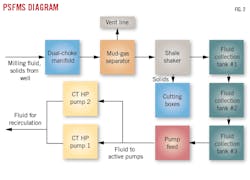
A purpose-built pressure, solids, and fluids management system (PSFMS) handled closed-loop solids and pressure control (Fig. 2). The system continuously removed solids and gas while maintaining well control during milling operations. The system included:
- a dual choke.
- a mud-gas separator.
- a dual-motion shale shaker with pretensioned screens.
- three interconnected fluid collection-tanks (each with 150 bbl capacity).
- a centrifugal feed pump.
The dual choke managed equivalent circulation density (ECD) of the hydrostatic well barrier. Milling operations could consume up to 900 bbl of fluid/30-ft interval, and the PSFMS significantly reduced total water and biopolymer consumption.
Milling BHA
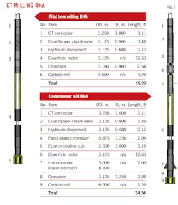
Trapped pressure below the cement plug can apply high compressive axial force on the BHA once the barrier is milled, resulting in compressional forces on the CT above rating. CT string integrity was protected by two-step milling. In the first step, a 4.5-in., six blade carbide mill BHA drills a pilot hole to safely release trapped pressure. The second step follows the pilot hole BHA with a 5.9-in. four-blade carbide mill BHA that incorporates a 3.0-in. underreamer with 8.3-in. cutting blades (Fig. 3). The reamer centralizes the bit and removes residual cement that could stick pipe from sloughing during subsequent perforation and ICR operations.
A 3.125-in. downhole motor provided 150-370 rpm and 900-1,070 ft-lb of torque with both BHAs at flow rates between 2.4 and 4.2 bpm.
Perforations
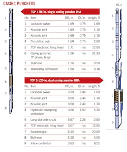
The single 9 5/8-in. casing had to be perforated at the 13 3/8-in. casing shoe to place cement in the B annulus. Multiwall perforations were required at shallower casing shoe levels to place cement into the C and D annuli. To minimize cement circulation pressures, maximum hole sizes were obtained by decentralizing guns for minimum standoff. The 9 5/8-in. casing punchers were run through the 6.31-in drift ID IRS, requiring a magnetic positioning device (MPD) at the bottom of the puncher with a spring positioner to decentralize the gun.
The 21-ft 1.56-in. OD single-casing puncher-gun contained charges with 0° phasing at 6 shots/ft (spf). A sealable swivel was included in the BHA to disengage the gun from the CT and let the MPD set the puncher gun with charges pointing at the wall. Two knuckle joints were added below the CT motorhead assembly to allow sufficient flexibility for gun alignment against the casing.
The 5.125-in. multiwall gun also had 0° phasing at 6 spf and included a hydraulically activated centralizer with half of the arms removed. A bowspring centralizer was positioned at the bottom of the gun to keep the gun against the casing. Fig. 4 shows configurations of both single-wall and dual-wall casing punchers.
Test coupon shots and full surface system testing with cement, steel, and representative standoffs confirmed that the outermost casing would not be damaged by the dual-wallpuncher. Average hole diameter was 0.31 in.
Guns were fired via electronic firing head for safety. The firing head contained no explosives and only could be fired when it received a coded pressure signature. The signature was independently verified by two separate processers in the head before firing. This system provided precise delay times, enabled firing abort commands at any time during the operation, and was insensitive to BHA pressure testing inside the pressure control stack.
Annular isolation
Once perforations established communication in the annulus, injection tests measured rate available for cement operations. A top-down squeeze method was used for good injectivity, and a circulation-squeeze method was used for poor or no injectivity. Circulation-squeeze required additional perforations above the established ones.
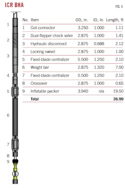
Inflatable packers provided zonal isolation, but the 6.31-in. drift of the IRS restricted full-bore mechanical packer access to setting depths, requiring a high-expansion ICR system (Fig. 5). The ICR was designed for single-trip operations and could be equipped with different sized inflation elements with OD from 2 1/8 in. to 3.75 in., depending upon application. The elements met the 3,000-psi maximum differential pressure requirement during cement placement into the annular space behind the 9 5/8-in. casing. The 6.31-in. full-bore ID in the IRS maximized pump-through for placement of over 100 bbl cement at 2 bpm. The tool was designed and manufactured to API 11D1 specifications.
Soft setting of the packer element by pressure buildup below the tool was avoided by configuring the inflation module with a solid seat and poppet valve. The solid seat created a closed system to protect the inflation element from debris in the CT, and the poppet provided maximum flow area for inflation. The solid seat could only be used for continuous seawater working fluid as other fluids would require change-out to a ball-seat configuration to enable spacer spotting above the packer while pumping the setting ball around the reel.
Staged inflation with specific hold points ensured that the element squared off across the casing and properly inflated with maximum anchoring while displacing any mud or debris on the casing ID. A hydraulic disconnect released the BHA from the ICR without pumping a ball to seat.
Cementing
Cement for the workovers required the following properties:
- Low rheology and sufficient thickening time to reduce friction pressures during cement placement with CT.
- Low sensitivity to seawater contamination in the well.
- Fluid loss below 50 ml/30 min to provide slurry stability during the squeeze.
- Stable fluid with no free fluid settling in the CT.
Simulations of cementing temperature and hydraulics modeled slurry conditions to determine cement formulation. The final recipe included antifoam, latex, fluid-loss control, dispersant, and retarder additives. Cement properties used for all annular spaces are shown in Table 1. Retarder loading was adjusted based on bottomhole static temperatures at different isolation depths.
Project execution
A dynamically positioned DP3 level MSV performed the work using a 750-ton tower, 440-ton deepwater crane, and 176-ton work crane. The vessel included a moonpool, a mechanical fully opening rig-floor door, a 7 3/8-in. IRS, two 10,000-ft heavy weather ROVs, and an overall 4,400-ton deck load.
A total of about 150 ft of cement plugs had to be milled out of both wells inside 9 5/8-in. casing through a 6.31-in. drift IRS with 2 3/8-in. CT. Milling was planned as a two-step process with a 4.5-in. pilot hole followed by a 5.9-in. mill with underreamer. WOB ranged from 6,000-6,500 lbf. Pump rate was 3.8 bpm during milling and 5.8 bpm during wiper trips. Pilot-hole drilling went as expected and mills showed minimal wear. Underreamer operations also went as planned, though harder and slower on Well 2 due to a foreign object in the cement.
On Well 2, a second underreamer run produced rubber, aluminum, and metal shavings in the returns. The source of this material was never identified. A third run with the mill only (no underreamer) milled through the remaining cement. A total of three runs were required to underream cement in this well, taking 32.75 hr. Despite the obstruction, both cement plugs were drilled ahead of schedule.
The diuta biopolymer milling fluid performed as intended, reducing friction and pump pressures. No overpulls or stuck pipe were encountered. Circulation pressures during pilot hole drilling ranged from 2,500-3,000 psi with 500-1,000 psi choke backpressure. During underreaming, pressures were 4,000-4,500 psi, with backpressure.
Cuttings removal in the riser was boosted by pumping additional viscosified fluid down the MSV 2 3/8-in. annular line at 2.0 bpm, adding about 60 ft/min of annular velocity in the riser to achieve a total of 191 ft/min. Average cuttings size at the shakers was about 0.03 in. (20 mesh) with largest cuttings about 0.20 in. (4 mesh).
The PSFMS managed ECD to maintain a hydrostatic well barrier. Pressure control included a dual-choke system with one choke serving as backup for uninterrupted milling, and the manifold included a diverter line for a third flow path in the event of dual choke failures or the system hitting pressure limits. The dual chokes also minimized downtime from cuttings plugging. A plugged choke could be cleaned while returns went through the alternative choke. Cuttings sizes at the choke were larger than in the shaker screens, confirming initial transport model expectations of maximum cuttings sizes.
The wells were drifted after milling to ensure removal of any residual cement sheath to ensure that the ICRs could set at depth. Once drift was confirmed, a ball was pumped to open a circulating sub in the underreamer BHA to displace the wellbore from residual 14.2 ppg oil-based mud (from original suspension) and milling fluid to seawater.
All intervals were perforated as planned. Perforations did not take any fluid into the B annulus in Well 1, requiring additional perforations above the first set for cement circulation squeeze. Circulation was established in the B annulus in Well 2 and C and D annuli in both wells, allowing for top-down squeeze and requiring no further perforations.
In Well 1, a 3.94-in. gauge ring was run below the element with 5.5-5.6-in. stabilizers placed above the BHA to mitigate damage to the inflatable element from upper perforation ledges in the lower interval. The remaining ICR runs did not require these safety measures. Three ICRs were successfully run per well.
All cementing operations occurred successfully within the expected time. Cement slurry was mixed and pumped on the fly and monitored by a nonradioactive densitometer and flowmeters for solid and liquid materials detection. Density was double-checked by periodic sampling and testing with a calibrated mud balance. Enough cement was pumped in each annulus to cover 200 ft. For each zone, once the annular space was full, the CT was stung out of the ICR and a cement plug was dumped on top of the retainer.
A total of 10 runs per well were required from start of drilling cement plugs to completion of the P&A operation. All work was completed safely, with no health, safety, or environmental incidents, and under authorization for expenditure (Table 2). The entire campaign took 7.6 days less than initially projected. The wells were abandoned in compliance with regulations.
Lessons learned
CT erosion was observed directly across upper perforations following the circulation-squeeze in Well 1. The failure resulted from abrasive 14.2 ppg oil-based mud producing from the 9 5/8-in. x 13 3/8-in annulus through the upper perforations when the mud was displaced to seawater before cementing. Revised procedures eliminated this risk by setting the ICR as close to the lower perforations as possible, minimizing volume displaced from the casing annulus. The pump rate was also minimized to reduce pressure drop across the perforations. Further procedural revisions kept the CT in tension once ICR was set to increase standoff from the perforations, and increased shot density in the upper perforations to decrease jet velocity across the CT.
Excessive mill wear was observed on the underreamer circulation ports, most likely caused by residual solids entrained in the milling fluid. Additional fluid filtration by fine mesh screens could eliminate this mechanism. On at least two occasions, debris plugged off the choke while milling, possibly because milling speeds were too high. Mitigation of this problem could be accomplished with automatic chokes for precise control of well pressure and self-cleaning features, avoiding aggressive rates of penetration while milling cement, and using mills with less aggressive cutting surfaces.
About the Author
Alex Procyk
Upstream Editor
Alex Procyk is Upstream Editor at Oil & Gas Journal. He has also served as a principal technical professional at Halliburton and as a completion engineer at ConocoPhillips. He holds a BS in chemistry (1987) from Kent State University and a PhD in chemistry (1992) from Carnegie Mellon University. He is a member of the Society of Petroleum Engineers (SPE).
