Test site advances hydraulic fracturing in the Permian basin
Scott Reeves
Jordan Ciezobka
Kent Perry
Gas Technology Institute
Des Plaines, Ill.
The hydraulic fracturing test site (HFTS) program is a research and development (R&D) partnership sponsored by the US Department of Energy, National Energy Technology Laboratory (DOE-NETL) and major and independent operator and service companies, managed by the Gas Technology Institute (GTI). The objectives of the HFTS program are to diagnose and understand hydraulic fracturing for field development optimization, minimize environmental impacts by reducing the number of new wells required for effective resource recovery, and improve extraction economics.
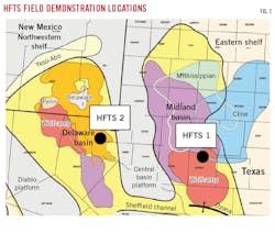
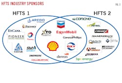
There are two test sites in the program, both in the Permian basin, separated by about 140 miles (Fig. 1). HFTS-1 is in Reagan County, Tex., in Midland sub-basin, operated by Laredo Petroleum. This site began R&D operations in late 2015 with Phase 1 activities completed mid-2018. Phase 2 activities began mid-2018 and are expected to continue through end-2020. HFTS-2 is in Loving County, Tex., in Delaware sub-basin, currently operated by Occidental Petroleum, formerly Anadarko Petroleum, with partner Shell Exploration & Production. This site began R&D operations in late 2018 and is expected to continue into 2021. Combined, DOE-NETL has sponsored the two sites with $20 million in funding. Industry has contributed $53 million in co-funding, and an estimated $600 million or more of in-kind assistance in the form of background data, wells of opportunity, technical and operational support, etc. Contributing industry sponsors for each site are shown in Fig. 2 and consist of major and independent Permian basin operators, major and independent service providers, and international companies seeking to gain insights into hydraulic fracturing for application to their indigenous unconventional resources. Collectively these industry sponsors represent more than 50% of operated wells in and gross production from the Permian basin.
Key features of the program are deployment of new and advanced diagnostic technologies to measure real-time fracture growth and final created fracture geometries, as well as testing and calibration of the technologies themselves. A unique and particularly insightful aspect of the test sites are research wells dedicated to coring through created hydraulic fractures, directly measuring fracture locations, fracture quantity, proppant concentrations, and other data. The wells are equipped with multiple discrete downhole pressure gauges to measure pressure depletion within the stimulated reservoir volume (SRV).
Since results are confidential to the program sponsors for a 2-year period, HFTS-1 Phase 1 results are just now becoming available via DOE-NETL. Access to these data and results can be found at https://edx.netl.doe.gov/group/hfts-1-phase-1-group. This article provides an update on various activities and diagnostics performed at each site, along with some of the newly available HFTS-1 Phase 1 results.
HFTS-1 activities, results highlights
The HFTS-1 site consists of 11 horizontal wells targeting the Upper and Middle Wolfcamp formations. Prior to completion of these wells, a vertical pilot hole was drilled in the project area and cored, logged and instrumented with an array of pressure and temperature gauges for long-term monitoring purposes. Over 450 hydraulic fracturing stages were subsequently pumped in the horizontal wells and selectively monitored with micro-seismic surveys, radioactive tracers, retrievable fiber optics, and tiltmeters. A slant core-well was subsequently drilled and cored through the SRV, collecting about 600 ft of core in Upper and Middle Wolfcamp formations, over an 86-ft vertical interval, and spanning two fracturing stages. This was the first such core through an SRV ever collected as part of publicly funded research.
The slant-well core information indicated that created fracture quantity and complexity were beyond what commercial fracture simulators can predict. The core indicated that creation of hydraulic fractures occurred in swarms only inches apart in some cases and the existence of propped fractures up to ¼ in. wide. In other cases, long intervals were left unstimulated. This finding suggests potential for refracturing in wellbore segments that were not effectively fractured with the original stimulation treatment.
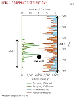
Another finding was that vertical extent of proppant-filled fractures was only a small fraction (about 5%) of the measured micro-seismic events. Fig. 3 shows vertical proppant distribution as derived from the Upper Wolfcamp core. The top horizontal axis shows number of fractures noted in the core, including both hydraulic (brown bars) and natural fractures (blue bars). The bottom horizontal axis shows number of proppant particles recovered (either 100 or 40/70 mesh size) from each sample on a per gram sample basis. The blue dot shows the relative vertical location of the Upper Wolfcamp treatment well.
Fig. 3 shows hydraulic fractures in the core at 7,700–7,720 ft, but with little proppant. The same is true for 7,745–7,750 ft. Significant proppant appeared only from 7,720–7,745 ft. In general, hydraulic fractures were created throughout the entire 50 ft vertical section, but significant proppant concentration was limited to a 30 ft section. Microseismic survey results, however, indicated a 600-ft vertical extent fracture geometry, therefore a 30-ft propped section of the reservoir represents 5% of the vertical fracture extent.
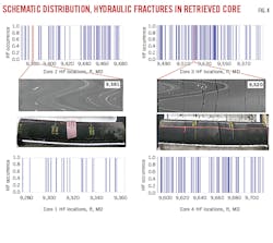
Fig. 4 shows created hydraulic fracture distributions in sections of four Upper Wolfcamp (UW) cores, starting with Core 1 in the left bottom and continuing clockwise with Core 2, 3, and 4. In Cores 2 and 3, selected 3 ft sections are highlighted and show the core section along with the CT scan (X-ray). In total, 436 ft of continuous core was collected in the UW containing over 600 total fractures of which 323 were identified as hydraulic fractures (blue bars in Fig. 4), resulting in about one hydraulic fracture every 1.3 ft. There are no hydraulic fractures in Core 2 at 9,381 ft. Core 3, at 9,520 ft, had eight hydraulic fractures in just a 3-ft section.
This clustering pattern was common and suggested that hydraulic fractures are created in swarms. In many core sections, HF fractures were dense and mere inches apart, and in other sections fracture voids spanned many feet. This fracture complexity and swarming is beyond modeling capabilities of current commercial fracture simulators. The swarming behavior also indicates that many sections of the reservoir are either unstimulated, or understimulated, leaving opportunity for future recompletions which target the fracture-void areas.
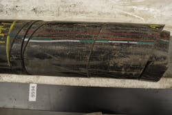
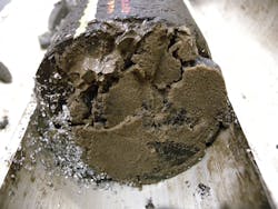
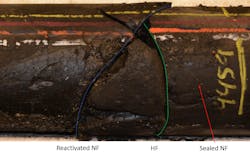
Fig. 5 illustrates additional cored hydraulic fractures and their complexity. The top photo shows core section with multiple hydraulic fractures without proppant. Some are a few inches apart and others have less than an inch of separation. Towards the left side of the core is an example of one fracture splitting into two (where the white line begins), or fracture bifurcation. Propagating hydraulic fractures, therefore, do not need to encounter a natural fracture to split into two or create multiple fractures. The middle picture shows the face of a proppant-filled fracture, and the bottom picture shows a hydraulic fracture interseting a natural fracture.
Fig. 5 Cored hydraulic fracture samples
Modeling complex fracture creation and production response is ongoing at Lawrence Livermore National Laboratory (LLNL) and Lawrence Berkeley National Laboratory (LBNL) using highly advanced research-grade numerical models coupled with high-performance computing platforms.
HFTS-1 also successfully tested a new patented variable-rate fracturing (VRF) method by which the fluid pump rate is rapidly changed, from a predetermined maximum rate to some significantly lower rate, and then rapidly increased back to the original maximum rate. These rapid changes temporarily produce a pressure pulse of hundreds to thousands of psi. This pulse propagates in the wellbore from surface to perforations. If the created pulse pressure, combined with bottom-hole pressure, is higher than perforation breakdown pressure, previously unopened perforations will open and initiate new fractures to maximize effectively stimulated rock volume. In the HFTS-1 test well, the rate pulses were executed throughout each fracture stage, including pad and slurry portions of each stage. Production from this well was compared with the offset wells that did not include VRF but had similar completion designs with the same or higher proppant loading. The VRF test well clearly outperformed the adjacent wells in both initial production rate and cumulative production, even after 24 months.
Air quality data gathered at HFTS-1 indicated that stimulation, flowback, and production of the 11 test wells did not affect local air quality. Methane, particulate matter (PM 10), volatile oil compounds (VOC), and nitrogen oxides (NOx) were measured 1,000 ft upwind and 1,000 ft downwind from the site before, during, and after site operations, and showed no deviation from baseline measurements during and after operations.
Five landowner-owned water wells within 5,000 ft of HFTS-1 were monitored for possible connection of groundwater and site operations. There was no detectable communication between the Edward-Trinity plateau freshwater aquifer and deeper hydrocarbon bearing zones activated by stimulation and production. Methane and BTEX (benzene, toluene, ethylbenzene, xylene) remained at non-detectable levels, and there was no increase in constituents related to hydraulic fracturing fluids.
Phase 2 tested the effectiveness of natural gas injection for enhanced oil recovery (EOR). An existing horizontal production well at a site about 1-mile northwest of Phase 1 was converted into an injector and instrumented with acoustic fiber optic cable for flow monitoring. Four existing offset horizontal production wells were used as beneficiary production wells. Prior to gas injection, a new slant core-well was drilled adjacent to the injection well to validate the character of created hydraulic fractures as measured at the Phase 1 site (260 ft of core was retrieved). This well was instrumented with pressure and temperature gauges for EOR monitoring. In addition, pressure gauges were installed in two vertical wells within the pattern. Gas was injected March-May 2019. Results from this EOR pilot should be available in 2021.
HFTS-2 activities
The HFTS-2 site consists of eight horizontal wells targeting the Wolfcamp “A” formation. Before completion of these wells, a vertical pilot hole was drilled within the project area, cored, logged, and instrumented with an array of pressure and temperature gauges for long-term monitoring. It was also instrumented with a permanent fiber optic sensing cable. The instrumentation for hydraulic fracture diagnostics was considerably more comprehensive than at HFTS-1 and consisted of:
- Quad combo and image logs in three of the horizontal wells.
- Permanent fiber optic sensing cable in two of the horizontal wells.
- Toe pressure and temperature gauges in two wells and diagnostic fracture injection tests (DFIT) in four of the horizontal wells.
- Microseismic arrays deployed in three of the horizontal wells to monitor fracture growth for all stages in another three wells.
Over 250 hydraulic fracturing stages were pumped and monitored in the horizontal wells, testing various perforation schemes and stimulation designs. Like HFTS-1, a slant core-well was subsequently drilled and cored through the SRV. It was the third such well in the HFTS program and collected about 950 ft of core across a 170-ft vertical interval spanning about 3.5 fracturing stages, providing additional detailed insights into the distribution and geometry of created hydraulic fractures. Initial data and results from HFTS-2 will begin public release in 2021.
Industry participation, technology dissemination
The HFTS industry sponsors provide insight and recommendations to the research program through active participation of dedicated staff on various technical committees. Each of the participating companies and DOE-NETL nominate multiple subject matter experts (SME) to advise on well completion, formation evaluation, fracture diagnostics, and other disciplines. Over the course of the program, hundreds of industry and DOE-NETL SME have engaged in the HFTS program. Technical overview meetings are regularly scheduled and number over 100. The broad level of outreach and hands-on participation is unprecedented amongst field research projects, with dissemination and real-time application of the technology ongoing through this active participation.
The authors
Scott Reeves ([email protected]) is executive director for exploration and production at Gas Technology Institute (GTI), Des Plaines, Ill. He holds a BS (1984) in petroleum engineering from Texas A&M University, and an MBA (1996) from Duke University, Durham, NC. He is a member of the Society of Petroleum Engineers (SPE).
Jordan Ciezobka ([email protected]) is a senior R&D manager at GTI. He holds mechanical and electrical engineering degrees (2005) from Purdue University, West Lafayette, Ind., and is a member of SPE.
Kent Perry ([email protected]) is director, energy supply and conversion at GTI. He holds a BS (1973) in petroleum engineering from Colorado School of Mines and is a member of SPE.
