CFD improves water separation efficiency in wet crude tanks
Saif F. Albluwi
Vilas S. Koleshwar
Maher M. Shariff
Lanre M. Oshinowo
Saudi Aramco
Dhahran
Saudi Aramco confirmed that inlet distributor design on an existing low-pressure degassing tank (LPDT) was the root cause of poor water separation at its gas-oil separation plant (GOSP). Despite the large size of LPDTs, oil-water separation efficiency was low, leading to additional investments in downstream oil treatment to remove water and meet product specifications. The existing inlet distributer design was not optimal and required development of new internals to enhance oil-water separation.
The performance of four internal tank options was evaluated and compared. Ultimately, the recommended design had multiple benefits for the facility debottlenecking project including increasing water separation performance by 28%, eliminating previous vibration issues caused by gas-liquid slugging, and optimizing scope and reducing capital expenditure (CAPEX).
Oil-water separation in LPDT is strongly influenced by water droplet size in the crude oil emulsion as well as the presence of gas in the feed stream. The header-riser type of inlet distributor causes gas to flow through the first three risers, forcing the liquid through the rest. The high gas velocities in the first three risers cause oscillations of feed flow (slugging conditions) that cause vibrations and fatigue failure of the inlet distributor. Despite large diameters of the LPDTs, computational fluid dynamics (CFD) confirmed that the distribution of the liquid phases within the tanks was suboptimal mainly due to short-circuiting, channeling, and dead zones.
CFD modeling identified the root causes of poor water separation in existing LPDTs and verified performance of proposed innovative tank internals to retrofit the LPDT and enhance water separation.
Background
New tank-internal designs based on CFD modeling addressed the shortcomings of a header-riser type inlet multiphase distributor to improve separation performance of an LPDT and increase dewatering of the produced crude. Inlets at a Saudi Aramco GOSP consist of four low-pressure production traps (LPPT) where gas-liquid separation occurs. Fig. 1 shows a process schematic of the GOSP inlet section and produced water handling facilities. The LPPTs are two-phase gas-liquid separators without water separation. Due to the short residence time, stable emulsion, and low temperature, no appreciable water separation was expected in the LPPTs.
Subsea pipelines deliver Arab Heavy Crude (AHC) from offshore. From the LPPTs, wet crude flows to the LPDTs. The LPDT is designed and operated as a three-phase (gas-oil-water) separator to degas the crude at near atmospheric pressure, settle liquid droplets from the gas, separate free water from the crude, and provide liquid surge capacity. The LPDTs also reprocess the recovered oily water from corrugated plate interceptors and recycled water from the wet crude dehydration train. The wet crude from LPDTs containing emulsified water is pumped to the wet crude handling system’s dehydrator and desalter units. Separated water from the LPDT is pumped to a water treatment facility. The gas from LPPTs and LPDTs flows to the respective gas compression systems.
Field testing established that 30% of the water in the AHC feed to GOSP is separated in the LPDTs. The water cut in the feed is forecast to increase three-fold, from 17% to 46%, over the next decade. With current water separation performance, wet crude from the LPDT will exceed the 30% water cut inlet specification to the downstream electrostatic dehydrator, creating a critical bottleneck in wet crude processing, constraining crude production capacity and crude quality from the GOSP.
Facility debottlenecking included an additional LPDT and additional crude pretreater units upstream of the dehydrator to reduce the wet crude water cut below 30% to the dehydrator. Enhancing water separation in the LPDT, therefore, could significantly impact the debottlenecking project by reducing scope and CAPEX.
The study underlying this article sought to design and evaluate a set of high-efficiency internals specifically configured to the LPDT to improve water separation through optimizing retention time distribution. CFD is commonly used to design and troubleshoot multiphase separators.1-4 As the water cut was forecast to continue increasing into the future, additional crude pretreaters were required. Recommendations emerged that not only impacted the ongoing debottlenecking project but also will help avoid unneeded CAPEX in the future.
A CFD study using both operating and design LPDT data provided a comprehensive solution to the deficiencies in water separation in existing and future LPDTs. The following approach was applied to the study:
- Determine water separation efficiency of existing internals (header and riser type inlet distributor) in the LPDT (base case).
- Propose alternate options for high separation efficiency internals to significantly improve the LPDT’s water separation efficiency.
- Quantify the water separation efficiency of the proposed high separation efficiency internals options.
- Analyze the results and compare the performance of each option against the base case.
- Select the best internals configuration with the most improved separation performance.
Low-pressure degassing tank
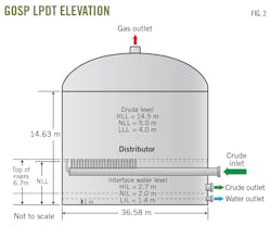
The existing low-pressure degassing tank (LPDT) is a large vertical cylindrical tank with sloped bottom (Fig. 2). The gas-predominant three-phase feed stream enters the LPDT through the 48-in. diameter inlet distributor and discharges the three-phase flow through 25 risers on top of the distributor pipe. The wet crude inlet nozzle is 3 m above the tank bottom. The 16-in. diameter risers begin at the centerline of the tank and are spaced with a pitch of 610 mm. The risers terminate at an elevation of 6.7 m. The oil outlet has an elbow internal to the tank terminating with a vortex breaker. The oil outlet nozzle is 48-in. in diameter. The water outlet is a half-pipe with the opening on the underside of the pipe. The 24-in. diameter water outlet nozzle is 1 m above the tank bottom.
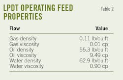
Winter is the worst-case condition for separation, with lower temperatures resulting in more viscous crude. Table 1 lists inlet flow rates for the heat and material balance (H&MB) design’s winter case. As the LPDT is operating at low pressure, a significant fraction of the LPDT feed stream is flashed upstream of the inlet distributor. Table 2 lists the properties used in the study.
The normal operating liquid level (NLL) is 5 m and is below the top elevation of the inlet distributor pipe (Fig. 2). The normal operating interface level (NIL) between the emulsion and water is 2 m. The risers terminate at an elevation of 6.7 m, within the range of the NLL to the high operating liquid level (HLL), and the liquid level is modelled at this elevation in all cases reported. The higher level increases the residence time but does not necessarily increase separation performance due to competing factors such as viscosity and droplet size. NIL can be increased to improve surge capacity for water in the tank.
CFD study methodology
The volume of fraction (VOF) multiphase model simulated the LPDT’s three-phase flow. This method determined the gas-liquid separation by sharp interface tracking and the oil-water interface is modeled as dispersed since the droplets are too small to resolve explicitly.
The realizable k-ε turbulence model determined turbulent multiphase flow. LPDT separation performance used a Lagrangian discrete phase model in which more than 4,000 200-μm water droplets were injected with the inlet flow into the LPDT and tracked stochastically by incorporating the dispersing effects of turbulence through the oil layer between the NLL and NIL to the crude outlet. Separation performance was determined by the ratio of the difference between the total droplets injected and the droplets exiting the LPDT through the oil outlet. The commercial CFD package ANSYS FLUENT 19.0 was used for all simulations.5
Base case
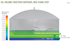
Fig. 3 shows distribution of oil and water in the mid-plane of the LPDT. The emulsified oil-water layer is above the water layer. The oil outlet vortex breaker is fully immersed in the emulsion layer. The water outlet is fully submerged in the water layer. The gas-liquid interface is shown in the interior of the inlet distributor pipe and in the tank and shows gas preferentially flowing through the first three risers and liquid flowing through the remaining risers. In the first riser there is almost 100% gas, with the gas fraction decreasing in the second and third riser as shown by the gas-liquid interface in Fig. 3.
The risers may get submerged in liquid due to a level control malfunction. This condition will release gas below the liquid level, causing gas-liquid mixing and turbulence at the liquid surface and leading to liquid entrainment in the gas.
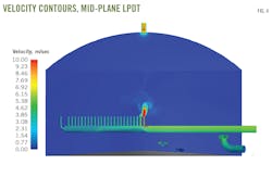
Fig. 4 shows the distribution of velocity in the mid-plane of the LPDT. The bulk of the gas enters the tank through the first three risers, leading to very high velocity in these risers particularly in the first riser as this is the path of least resistance for the gas flow. A separate transient VOF simulation determined the time-varying phase distribution and slugging potential in the inlet distributor. The high gas velocities in the first three risers cause oscillations of feed flow (slugging conditions) that cause vibration of the inlet distributor (header and risers). The vibration in the inlet distributor structure has the potential to cause fatigue failure of the supports. There have been previous failures of the distributor supports and these simulations verify the observations and plant experience. Vibrations can also be transferred to the shell to vibrate the entire tank beyond acceptable levels, potentially compromising tank integrity.
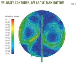
Fig. 5 shows velocity contours overlaid with velocity vectors plotted on a plane 5 m above the tank bottom. The many large-scale vortices are indicative of asymmetric and uncontrolled flow patterns in the LPDT. This swirling flow increases liquid phase intermixing and the liquid short-circuits to the outlet, reducing residence time.
Fig. 6 shows the streamlines and the complex three-dimensional flow in the LPDT. There are many streamlines directly flowing from the risers to the oil outlet illustrating flow short-circuiting and insufficient time for separation. The high-velocity flow from the first riser causes high turbulence and fragmentation of the liquid droplets, contributing to poor separation. The flow patterns in the LPDT show flow distribution facilitates degassing due to the large free-surface area. Liquid circulation, however, shows limitations in liquid-liquid separation.
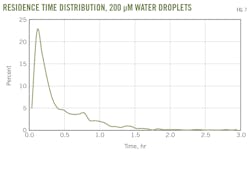
Determining the residence time distribution of 200-μm water droplets exiting the LPDT oil outlet allowed evaluation of LPDT separation performance (Fig. 7). A significant amount of water appears in the oil outlet soon after entering the tank. This indicates significant short-circuiting of the flow to the oil outlet. A sharp peak appears at 15 min before the theoretical retention time followed by a long tail indicative of the large recirculation regions in the tank. The absence of internals produces an asymmetric and uncontrolled flow pattern in the LPDT, leading to a wide distribution in residence time. The separation performance of the tank is impacted adversely by inlet distributor design.
Base case analysis demonstrated that improvement in separation performance would be achieved with new tank internals optimized to delay water arriving at the oil outlet and reduce the spread or standard deviation in the residence time distribution. Four options of tank internals were evaluated and compared against the base configuration. Geometric details of each are not described here as the authors are seeking patent protection.
The existing header-riser configuration will be replaced by the best performing tank internals among the four options studied, with cost as an important consideration. Further improvement to these configurations may be considered in future studies.
Performance ranking
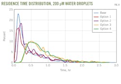
Fig. 8 plots the residence time distributions of 200-μm water droplets exiting the LPDT through the oil outlet for the base case and the four new options. Options 3 and 4 have the largest impact on delaying the appearance of water at the oil outlet. These internal configurations decrease the spread in the residence time distribution to promote increased separation of water from the crude.
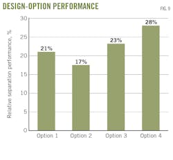
Fig. 9 illustrates the separation performance of each internal option relative to the base case in the separation of 200-μm water droplets. All options significantly increase separation performance relative to the existing LPDT internals’ configuration. Option 1 improved the fraction of water droplets captured. Option 2 is a variant of Option 1 and leads to worse separation performance than Option 1.
Option 3 is an improvement. But the most significant increase occurs with Option 4, a variant of Option 3 with a longer pathway for the liquids from a new inlet distributor to the oil outlet. The Option 4 configuration converts the unconstrained cylindrical domain into rectangular cross-sectioned pathways through the LPDT to decrease short-circuiting and reduce the spread in the residence time distribution. It minimizes the amount of recirculation and dead zones, further tightening the residence time distribution and improving liquid-liquid separation.
Additional internals could lead to further improvements in performance but will increase weight and cost. Performance benefits will factor into the cost-benefit analysis for a decision on the most cost-effective solution .
Design guidelines
The following elements should be considered in LPDT design:
- Suitable internals for efficient separation of gas from bulk liquid phase and separation of water from the oil phase, irrespective of the LPDT’s size.
- Design, placement of the LPDT internals; validated by CFD study.
- Water droplet size distribution as a design input.
- Identification of solids in liquid stream before design.
- Confirmation of LPDT inlet piping flow regime, particularly slug flow, and accounting for it in internals design.
- Minimized shearing of the feed stream.
References
- Kharoua, N., Khezzar, L., and Saadawi, H., “Application of CFD to Debottleneck Production Separators in a Major Oil Field in the Middle East,” SPE-158201, SPE Annual Technical Conference and Exhibition, San Antonio, Oct. 8-10, 2012.
- Boschee, P., “Challenges in the Design of Separators,” SPE Oil and Gas Facilities, Vol.. 2, No. 6, December 2013.
- Oshinowo, L., Elsaadawy, E., and Vilagines, R., “CFD Modeling of Oil-Water Separation Efficiency in Three-Phase Separators,” Progress in Applied CFD, Oslo, SINTEF Academic Press, 2015, pp. 207-216.
- Read, A., “The Savvy Separator Series, Part 7 - Introduction to CFD for Separator Design,” SPE Oil and Gas Facilities, Vol. 5, No. 3, June 2016.
- ANSYS Inc., “ANSYS FLUENT™ Theory Guide, Release 19.0,” ANSYS Inc., Canonsburg, PA, 2018.
The authors
Saif F. Albluwi ([email protected]) is a specialist currently heading the Gas Processing Unit at the Process & Control Systems Department (P&CSD) in Saudi Aramco. He holds a BS in chemical engineering from the University of Birmingham, UK. He is an Associate Member in IChemE and has almost 13 years experience with Saudi Aramco specializing in oil and produced water treatment. He also has two patents (1 granted, 1 filed) in the field of oil and water treatment.
Vilas S. Koleshwar is engineering specialist at Process & Control Systems Department in Saudi Aramco. He holds B.Tech degree in chemical engineering from IIT, Kharagpur, India, and professional engineer membership with the Association of Professional Engineers and Geoscientists of Alberta, Canada. He specializes in oil and water treatment and has over 35+ years of professional experience in the oil and gas industry in India, Kuwait, Canada, and Saudi Arabia.
Maher M. Shariff is a senior scientist at Saudi Aramco R&D Center, Oil and Gas Treatment Division. He holds a BS in mechanical engineering from Bradley University Peoria; a master of science in mechanical engineering from Washington University, St. Louis; a master of engineering from Vanderbilt University, Nashville; and a PhD from Wichita State University in association with the National Institute for Aviation Research. Dr. Shariff worked for Cessna Aircraft Company in the US and Saudi Arabian Basic Industries Corporation (SABIC) in Saudi Arabia. He was also a visiting research scholar at Tulsa University’s Fluid Flow Projects (TUFFP). He was the vice-chair of ASME, and publicity and events director for American Chemical Society in Saudi Arabia.
Lanre Oshinowo is a science specialist in the Research and Development Center at Saudi Aramco. He is currently developing novel CFD and simulation applications to improve the design and operation of oil and gas processing facilities. Dr. Oshinowo holds a PhD (1997) in chemical engineering from the University of Toronto, Canada, is a member of AIChE and SPE, and is a licensed professional engineer in Ontario. He previously held leading technical roles at ConocoPhillips, ANSYS, HATCH and Fluent in the USA and Canada.


